Specify settings for contour lines and section graphics for legacy toposurface elements.
To open the Toposurface Settings dialog
- Select the toposurface
 Modify|Topography tabSurface panel drop-downToposurface Settings.
To display contour lines and define intervals
- For Contour Line Display, select At Intervals of.
- Enter a value for contour line intervals.
- For Passing Through Elevation, enter a value to set the starting elevation for contour lines.
By default, Passing Through Elevation is set to zero. If you set the contour interval to 10, for example, lines display at -20, -10, 0, 10, 20. If you set the Passing Through Elevation value to 5, lines display at -25, -15, -5, 5, 15, 25.
To see contour lines, open a site view.
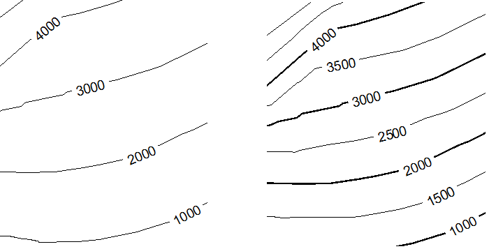
To add custom contour lines to a toposurface
- Click Insert for each set of custom contour lines.
- To create one custom contour line, do the following:
- Under Additional Contours, for Range Type, select Single Value.
- For Start, specify the elevation for the contour line.
- For Subcategory, specify the line style for the contour line.
- To create multiple contour lines in a range, do the following:
- Under Additional Contours, for Range Type, select Multiple Values.
- Specify the Start, Stop, and Increment for the additional contour lines.
- For Subcategory, specify the line style for the contour lines.
If you clear At Intervals of, custom contour lines still display.
To specify section graphics
- For Section cut material, select a material to use to display the site in a section view. Appropriate materials include Site-Earth, Site-Grass, and Site-Sand.
- For Elevation of poche base, enter a value to control the depth of the cross-section of earth, for example, –30 feet or –25 meters. This value controls the poche depth for all topography elements in your project.
To see changes to section graphics, open a section view.