Use the synchronization process via the Advance Steel extension to update the Revit model with changes made in Advance Steel.
Synchronization is a process that allows you to update your modifications using the .smlx format, without having to re-import the entire structure.
The Synchronization workflow:
- Export your model with structural elements from Revit to Advance Steel using the extension, in .smlx format.
- If you make modifications to the Revit model, re-export the modified model from Revit to a different .smlx file.
- Go back to Advance Steel and load the modified .smlx file: In the Synchronization dialog

 (Load).
- The modified .smlx file is compared to the already loaded model. All modifications between the two versions of the model will be displayed. The modifications for each object will appear in a list which can be filtered.
- The synchronization process marks all the new objects or the existing ones that had geometrical changes (section size, positioning, rotation, etc.) as modified.
- You can apply the modifications partially or completely using a series of options.
Highlight selected elements in canvas
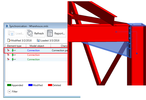
To quickly spot the Revit model objects, you can double-click on the lines (modified or deleted) inside the synchronization dialog to highlight and zoom in on the objects in the model. If the element is not visible in the current view, then a view where the element is visible will be opened. In the case when the element is not visible in any project view, a warning message will appear notifying you that a view could be found:
Synchronization and Project Units
The Synchronization dialog works with the units and tolerances set in the Revit Project Units dialog. You can manage the number of modified lines that are displayed inside the synchronization dialog by modifying the unit tolerance in the Project Units dialog.
Main tick boxes with applied filters
In the Synchronization dialog the Main tick boxes work with applied filters. If objects are selected using the filters and a main tick box is activated, only those lines will have the individual tick box selected.
| Sync dialog - Main tick boxes | Sync dialog - Selection filters |
|---|---|

|

|
In the following images there is an example:
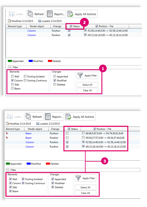
Column elements were selected to be displayed
 . Status main tick box was selected
 . All objects were made visible again
 .
.
In the dialog you will see that only the Column lines have the individual tick boxes selected.
Position and offset display in the synchronization dialog
The Synchronization dialog displays both Position and Offset changes in a single modification line. You are prompted with the coordinate points of the start and end points of the system axis. This applies to all linear elements, including curved beams. Straight axes are defined by 2 points with the following syntax "0,0,0->1500,0,0" and curved beam axes are defined by 3 points "0,0,0->1500,1500,0->3000,0,0", where the middle coordinates represent the midpoint of the curved beam.

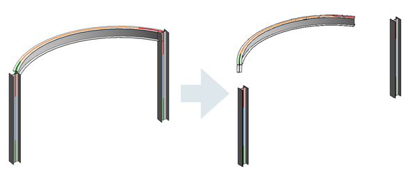
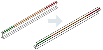
Beam and column rotation in the Revit Synchronization dialog
Beam and Column section rotations are spotted and applied by the Synchronization dialog in Revit. The change is displayed with the word Angle.

Synchronize plates in Revit
The following plate modifications can be synchronized in Revit:
- Position
- Shape
- Thickness
- Material
In order to display the above mentioned capabilities, a model from Revit was exported and then imported in Advance Steel. Here, several connections were modeled between the structural elements. After this step, the model was exported again, this time from Advance Steel, and the plate objects were synchronized in the initial Revit model.
See example in the images bellow:
| Advance Steel model | Revit model | Revit synchronization process | Synchronized Revit model |
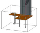
|
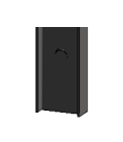
|
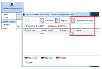
|
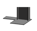
|
- Position
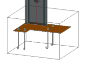
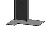
In the following example the corner base plate was rotated by 90 degrees in the Advance Steel model.
When this modification is synchronized back in the Revit model the difference is spotted as a position change.
The Synchronization dialog compares the coordinates of each point that defines the plate and displays them at the interface as: "-0.85,-100.36,-1.36 à -0.85,-97.96,-1.36 à 0.07,-100.36,-1.36 à …".
If the change is applied, the corner base plate is rotated to the new position.
| Advance Steel model | Revit model | Revit synchronization process | Synchronized Revit model |
|

|

|
|
- Shape
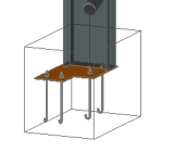
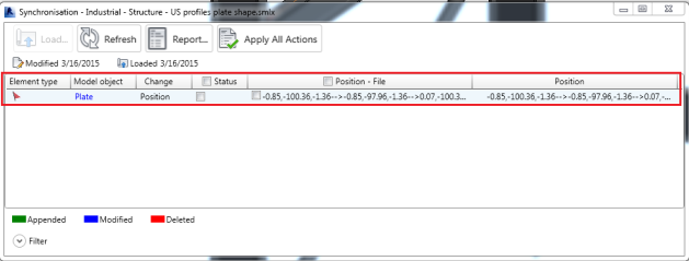
In the next example, the base plate shape was modified in the Advance Steel model. When this modification is synchronized back in the Revit model the difference is also spotted as a position change. The Synchronization dialog compares the coordinates of each point that defines the plate and displays them at the interface as: "-0.85,-100.36,-1.36 à -0.85,-97.96,-1.36 à 0.07,-100.36,-1.36 à …" .
If the change is applied, the plate shape is modified accordingly.
| Advance Steel model | Revit model | Revit synchronization process | Synchronized Revit model |
|

|
|

|
- Thickness
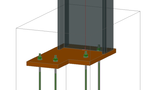
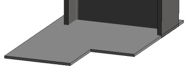
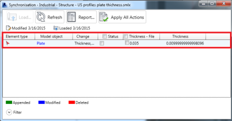
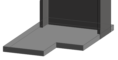
In the following example the plate thickness was increased in the Advance Steel model. When this modification is synchronized back in the Revit model, the difference is spotted as a thickness change. If the modification is applied, the plate thickness is changed according to the new value.
| Advance Steel model | Revit model | Revit synchronization process | Synchronized Revit model |
|
|
|
|
- Material
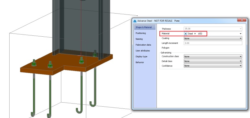
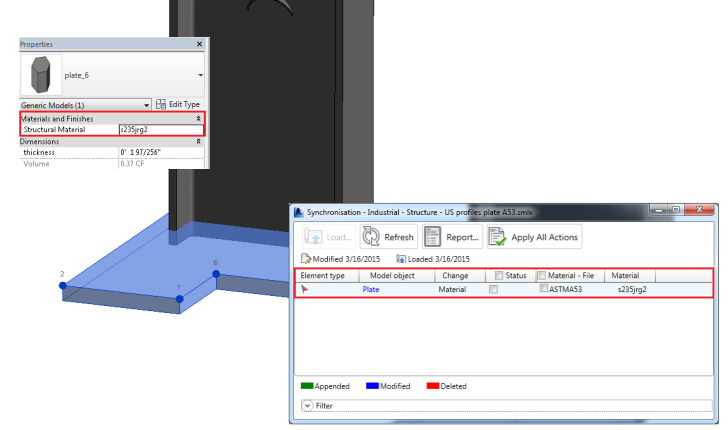
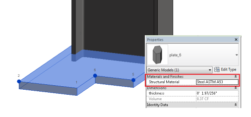
In the following example the base plate material was modified to "Steel ASTM A53" in Advance Steel. This modification was then synchronized in the Revit project. The difference is spotted as a material change. If the modification is applied, the plate material is changed according to the new value.
| Advance Steel model |
|
| Revit model sync process |
|
| Synchronized Revit model |
|