Rebar couplers connect adjacent rebar while simplifying the design of reinforced concrete.
Couplers interact with the reinforcement bars that they connect by modifying their physical dimensions. Couplers apply end treatments to connected rebar according to the connection needs of the coupler. Bar geometry shortens to accommodate the connection with the coupler.
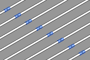
Coupler families have customizable geometry. You can create and modify nearly any type of coupler with separate representations in 2D and 3D views. Type parameters define dimensions, the sizes of bars to which the coupler connects, and the end treatments that are applied to the rebar.
Coupler visibility in section views
- Can be added to schedules.
- Are available to groups and assemblies.
- Are exportable to various formats.
- Propagate across rebar in sets.
- Can be assigned a host partition with unique coupler numbers.
- Can be viewed unobscured in a host. However, couplers are always viewed as solids in 3D views.
- Can be tagged.
Coupler vewing angles
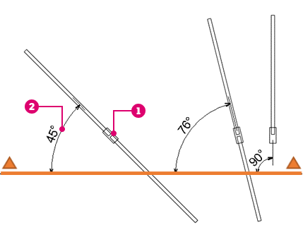
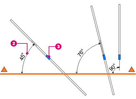
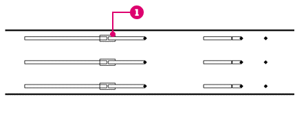
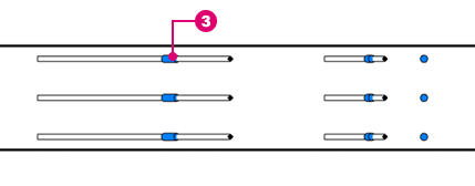
The coupler geometry is automatically rotated to show in the same way in 2D views, when the Align to View option is checked. Couplers are also hidden when Aligned to View and the angle between the section (or any view) plane and bar direction is above 75 degrees.
In 3D views, the coupler geometry is always aligned to the bar end. When rotating the coupler, this is the default position.
Example showing couplers aligned to the end of bars in a free form rebar set.
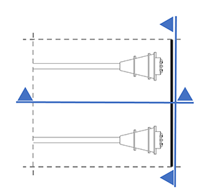
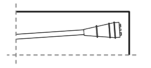
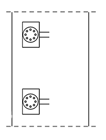
To display the coupler in a realistic way in 2D views, regardless of the view angle, you can edit the coupler family and uncheck the Align to View option. Make sure the solid geometry in the family is set to display in all views and delete all the symbolic line geometry.
To make any solid element in the family to show in all views, you can edit the family, select solid element, go to the properties palette  Visibility / Graphics Overrides and check the Project Plan, Section and Elevation views option.
| Family Configuration |
|
|
|
| Plan |
 |
 |
|
| Section |
 |
 |
|
| On the left side of the image, the coupler is visible for view angles ≤ 75°. | On the right side of the image, the coupler is not visible for view angles > 75°. | The coupler is visible regardless of the view angle. | |
 The coupler shows the symbolic representation in 2D views.
 The angle between the bar and the section view plane.
 The coupler shows the solid representation in all views.
| Plan View | Section 1 | Section 2 |
|---|---|---|
 |
 |
 |