Revit LT creates automatic dimensions to help control your design intent. These automatic dimensions are not displayed by default.
To turn them on, select Automatic Sketch Dimensions on the Annotation Categories tab of the Visibility/Graphic Overrides dialog. You can then modify the dimensions or create your own dimensions using the Dimension tools. You can also lock dimensions to keep a distance constant. This is useful if you plan to have several sizes of the family and want to keep certain dimensions constant while the family changes size.
Effects of Automatic Dimensions on Your Geometry
When automatic sketch dimensions constrain geometry to reference planes, you may see some unexpected behavior in your project. The automatic sketch dimensions are Revit LT's way of solving how to grow or shrink geometry based on changes in value of a family parameter.
Example
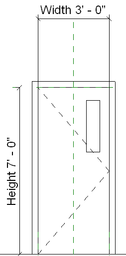
You have added a rectangular window to a fire door that has a labeled dimension for the width, but you have not dimensioned the window.

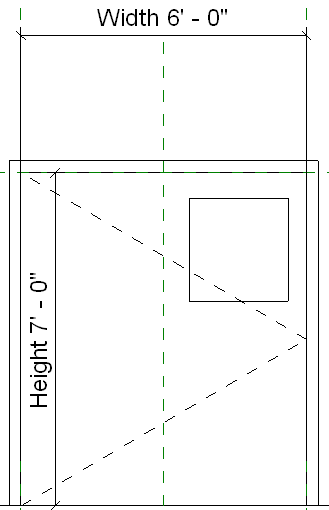
You decide to change the width of the door, but you want the window width to stay the same. You expect its position to remain unchanged; however, observe what happens when you increase the width of the door using the Family Types tool.

In this example, the window is constrained to the centerline of the door and the right side of the door panel, both of which are represented by reference planes. The window's position remains fixed relative to those reference planes.
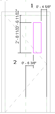
To see the automatic sketch dimensions, edit the sketch of the window and turn on the visibility of the dimensions. You will see how the vertical sketch lines of the window are dimensioned to the center and right reference planes.

Image legend:
- Auto sketch dimension to right reference plane.
- Auto sketch dimension to center reference plane.
To achieve the desired results, add locked dimensions. For example, you could add a locked dimension for the width of the window and a locked dimension from the window to the right reference plane.