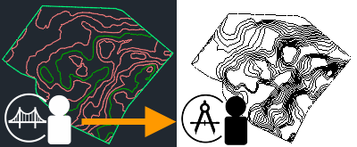
Create a link to topography that a civil engineer produced using Autodesk Civil 3D.
 Video: Link Topography to the Building Model

Topography provides context for the building model in Revit LT. If the civil engineer later updates the topography, you can reload the link to see the changes in the Revit model.
To link topography
- Prepare
Autodesk Desktop Connector.
Note:
Check the Desktop Connector version you have installed on your computer. Link Topography works with version 14.12.0.1491 and newer.
Watch this help topic for updates on the latest released versions.
- In
Civil 3D, prepare the topography as follows:
- Create topography for the project.
- Publish surfaces to
Autodesk Docs.
The process to publish surfaces can take a few minutes. When ready, the topography data displays in the Autodesk Docs folder.
- (Optional) In Autodesk Docs, review the topography.
- In
Revit LT, link the topography to the current model as follows:
- Specify coordinates for the building model.
Define the model's survey point using grid (GIS) coordinates from the civil engineer. This strategy ensures accurate positioning of the model on the linked topography.
If you skip this step, the linked topography is placed center to center with the model, and you must position it manually. See About Positioning Linked Topography.
- Open a plan view or a 3D view for the building model.
Use the Visibility/Graphics dialog to make sure that toposolids will display in the view. For example, the site plan view displays toposolids by default.
- Click Insert tab
 Link panel
 (Link Topography).
- In the Link Topography dialog, navigate to the topography.
Select the appropriate Autodesk Docs project and folder. The dialog lists topography that contains surfaces, indicated by the
 icon.
icon.
- Select the desired topography, and click Link.
- Specify coordinates for the building model.
Visibility/graphics: The toposolid displays in the current view based on its Visibility/Graphics settings. Use the Visibility/Graphics dialog to control the toposolid display in other views.
Multiple surfaces: If the linked topography contains multiple surfaces, each surface is treated as a separate element in the link. Press Tab to select an individual toposolid. See Select Elements in a Linked Model and About Working with Linked Topography.