Copy an Existing 2D Frame to Create a 3D Structure
Select Start from the Layouts drop-down list.
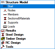
The layout updates to its initial state.
Expand the list of views at the bottom of the drawing area, then select the 3D view.
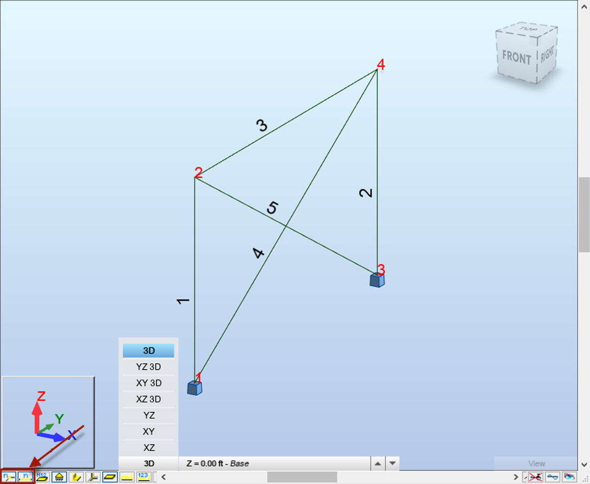 Note: If the member and node numbers do not display, select the
 and
and  quick launch buttons located in the far-left, bottom of the page.
Click Geometry > Properties
 Sections from the Standard toolbar.
Select the HP 12x63 section.
Note: The new beams are automatically created during the copy process.Select Close.
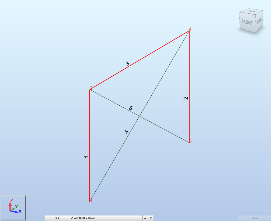
Do all of the following from the horizontal toolbar:
Enter the node number for the beam in the Node Selection box separated by a space (e.g., "2 4"), and press Enter.
Enter the column and beam numbers separated by a space (e.g., "1 2 3"), and press Enter.
Click Edit > Edit >
 Move/Copy... from the Standard toolbar.
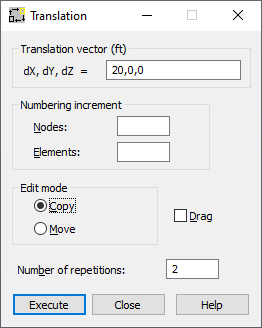
Enter 20, 0, 0" in the Translation vector field.
Verify that the Edit mode field is set to Copy.
Enter 2 in the Number of repetitions field.
Select Execute, then Close to exit the Translation dialog box.
Select
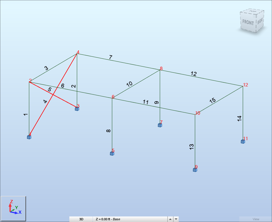
 to view the entire structure in the viewer. The 3D frame structure displays.
 Note: In this structure, beam numbers 6,7, 11 and 12 were created automatically by the Drag option.
In the drawing area, select the bracing's number 4 and 5. To do this, select a bracing, then hold the Ctrl key and select the other bracing. The selected bracings display highlighted.
Click Edit > Edit >
Move/Copy... from the Standard toolbar.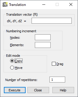
Enter 40, 0, 0" in the Translation vector field.
Verify that the Edit mode field is set to Copy.
Enter 2 in the Number of repetitions field.
Select Execute, then Close. The structure displays in the graphic viewer.
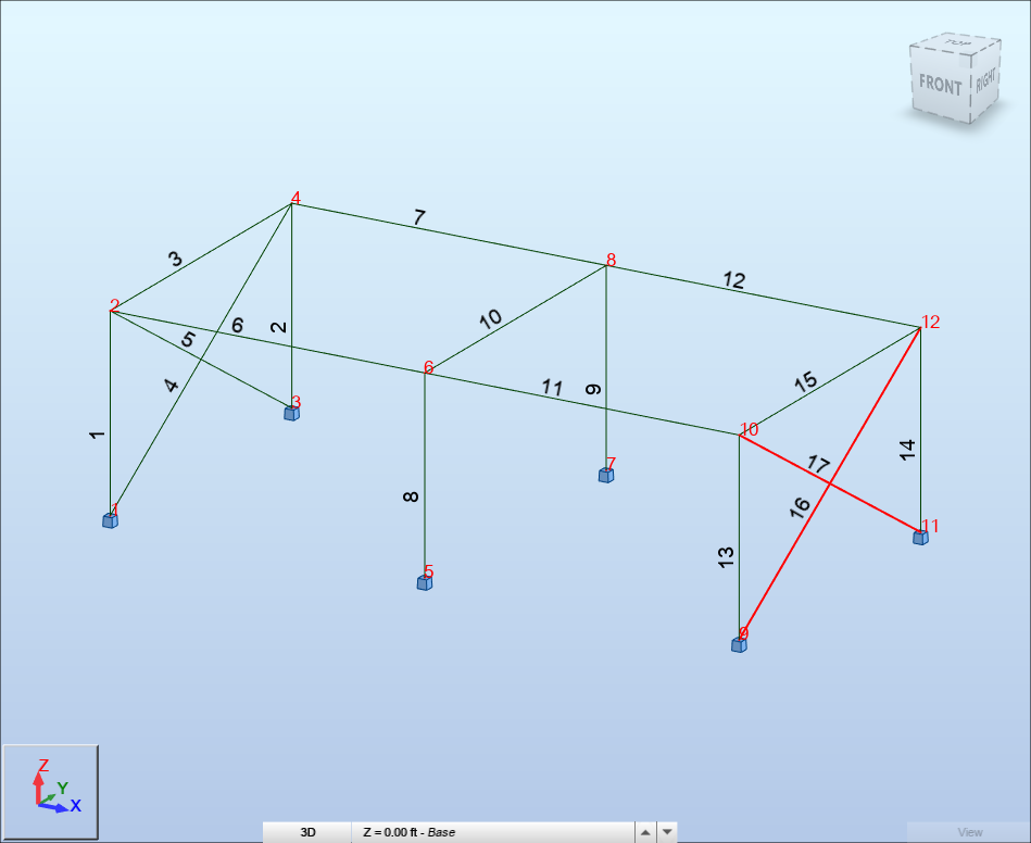
Click in the drawing area to remove the bracing numbers 16 and 17.
Save the project.