Spatially Varying Loads
In certain circumstances, it is useful to specify a non-uniform profile for velocity, volume flow rate, or temperature boundary conditions. In addition to the default uniform profile for these boundary condition types, you can select from one or more varying distribution methods to more closely represent the physical distribution of the quantity entering the physical domain.
Variation Types
In addition to the default Constant variation, the following variation methods are available:
Fully Developed
The Fully Developed profile is an option for the Velocity (Normal direction) and Volume Flow Rate boundary conditions. It is available for the following planar surface types: quadrilateral (4 edges), circular (1 edge or 2 edges), or triangular (3 edges).
Unless the objective of an internal flow simulation is to study entrance effects, most pipe and duct flows are assumed to be fully developed. The fully developed flow profile is generally more physically realistic than a uniform (slug) profile. By using it, you can eliminate the need to add an entrance length upstream of the model inlet.
To apply a Fully Developed velocity profile, select Fully Developed from the Spatial Variations list on the Boundary Conditions quick edit dialog box.
To apply a Fully Developed volumetric flow rate profile, check Fully Developed on the Boundary Conditions quick edit dialog box.
Fully Developed is not available for the temperature boundary condition.
Linear Variation
The Linear Variation provides a way to vary a velocity or temperature boundary condition in one dimension across a boundary surface.
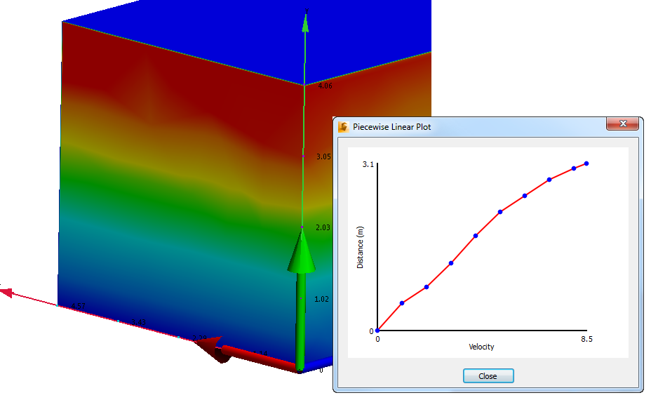
The wind flow around architectural structures (buildings) often has a parabolic distribution increasing from ground level through the height of the buildings. Accounting for this velocity profile is essential for accurately accounting for wind shear effects. You can use the Linear Variation flow profile to specify velocity at specific locations using a piece-wise linear distribution.
In electronics, the flow exiting from an electronic enclosure often enters an adjacent enclosure. The temperature of the air is not uniform as a result of the components within the enclosure. Instead of specifying a constant temperature at the inlet of the adjacent enclosure, specify the distribution using a Linear Variation of temperature value across the inlet.
To assign a linear variation to either a velocity or temperature boundary condition
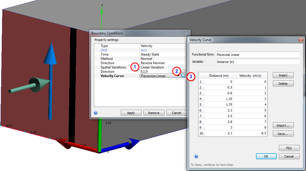
- From the Boundary Condition quick edit dialog box, select Linear Variation from the Spatial Variations row.
- To set the variation direction across the selected surface, either key in a unit vector in the Direction row, or click the value in the Direction field to open the Vector dialog. Select the vector direction or a surface that is normal to the intended direction.
- To define the variation, click Piecewise Linear. Enter the values and distances in the table. The distance increases in the defined direction of the variation. Autodesk® CFD ignores values specified at distances that exceed the dimension of the surface.