Using Compact Thermal Model Materials
To Assign a Compact Thermal Material
- Open the Material quick edit dialog. There are several methods:
- Left click on the part, and click the Edit icon on the context toolbar.
- Right click on the part, and click Edit...
- Right click on the part name under the Materials branch of the Design Study bar, and click Edit....
- Click Edit in the Materials context panel.
- Select one or more parts.
- Select the database from the Material DB Name menu.
- Select Compact Thermal Model from the Type menu.
- Select the material from the Name menu.
- Click Apply.
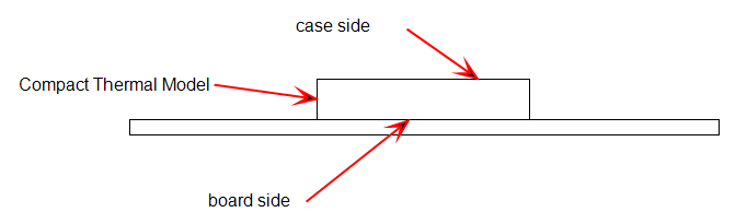
The compact thermal model must contact either a PCB material or a solid material with “PCB” in its name. ("PCB" must be in English.) From this, the orientation of the device is determined automatically.
The side of the component touching the PCB material is the board side, and the board node is at the center of the board surface of the component. The opposite side is the case side.
To Create a Compact Thermal Material
Only two parameters are required to define a two resistor Compact Thermal Model on the Material Editor:
- Theta JB: the resistance between the junction and the board
- Theta JC: the resistance between the junction and the case
- To open the Material Editor, click Material Editor on the Materials context panel.
- Click the List button.
- Right click on a custom database, and select New material. Select Compact Thermal Model. Specify a Name.
- Click either the Theta JB or Theta JC button.
- Enter a value and appropriate units. (Note that the only available variation method is Constant.)
- Optionally, click Save.
- Click OK. The new material is available when the Materials quick edit dialog is opened.
Note: Values for the resistances (Theta JB and Theta JC) can often be obtained from the component manufacturer’s specifications.
Related Topics
Compact Thermal Modeling Guidelines
Example showing creation of a Compact Thermal Material
Example showing assignment of a Compact Thermal Material