Internal Fans
Internal fans simulate an axial momentum source within the interior of the geometry. Fans can have a constant flow rate, or the flow rate can vary with a head-capacity curve so that the fan operating point depends on the pressure drop through the device.
It is better to use an Internal Fan instead of a Rotating Region if you your focus is on moving the air within the system, and are not concerned with the physical performance of the blade design or blade-interaction effects.
To Assign an Internal Fan
Open the Material quick edit dialog. There are several methods:
- Left click on the part, and click the Edit icon on the context toolbar.
- Right click on the part, and click Edit...
- Right click on the part name under the Materials branch of the Design Study bar, and click Edit....
- Click Edit in the Materials context panel.
Select one or more parts.
Select the database from the Material DB Name menu.
Select Internal Fan/Pump from the Type menu.
Select the material from the Name menu.
To specify the flow direction, open the pop-out dialog on the Flow Direction line, and select either the Global X, Y, or Z axes. Alternatively, click the Select Surface button, and select a surface. The flow is normal to the selected surface.
To change the flow direction, click Reverse.
If the fan is to be temperature dependent, click the Thermostat button, and define the temperature behavior as described below.
Click Apply.
Example showing assignment of an Internal Fan Material
Internal axial fans should not be placed on an external boundary. Likewise, it is not good practice to apply boundary conditions to any surface of an internal fan material. Doing so may cause convergence difficulties and will affect the flow rate reported in the summary file. If an internal fan contacts an external boundary, it is better to either create an extension onto the fan inlet (so that the boundary condition is not applied directly to the fan) or simply use an external fan boundary condition instead of an internal fan material.
Parts assigned an internal fan material should not be extrusion meshed. The Solver does not support internal fans with extruded elements.
Thermostatic Controls
This feature allows internal fans (and blowers) to be dependent on a temperature within the model. The fan will run as long as this “trigger temperature” is above (or below) a pre-defined cut-off. When the temperature at the thermostat location is below (or above) the cut-off, respectively, the fan will not run.
Check the Thermostat box on the Internal Fan/Pump Materials task to expand the Internal Fan Thermostat controls. This dialog allows for specification of a Trigger temperature and a thermostat location.
- Click the Thermostat box to activate an internal fan thermostat.
- Set the thermostat location by opening the Location pop-out, and selecting a surface on the model.
- Click Select Surface, and pick a surface in the model. The centroid will be the sensing location.
- Specify the Trigger Temperature and units.
- Select the Trigger Type (fan dependence on temperature): Below Trigger (to keep things warm) or... Exceed Trigger (to keep things cool).
- Click Apply to finish.
The average temperature on the surface is used as the sensing temperature. (Any surface in the model can be used.) While this dialog is open, the interface allows for the selection of a surface. Only one surface can be used as a sensing surface, so selecting a new surface will update the selection list. The surface ID is written in the space called “Location,” and the surface in the model is highlighted.
To Create and Edit an Internal Fan
- To open the Material Editor, click Material Editor on the Materials context panel.
- Click the List button.
- Right click on a custom database, and select New material. Select Internal fan/pump. Specify a Name.
- Click the property button that is to be defined.
- For each property: Select the Variation method, enter the appropriate value and units, and click Apply.
- Optionally, click Save.
- Click OK. The new material is available when the Materials quick edit dialog is opened.
The Default material database contains at least one instance of every material type. A convenient way to create a new material is to use a Default material as an example. Because these materials are read-only, use the Material Editor to copy the original into a custom database, and modify the copy. For more about creating a material from an existing material...
Example showing creation of an Internal Fan Material
Guidelines
- A Fan material definition does not reference specific Cartesian components. Instead, the Through-Flow-Rate is entered. The specific Cartesian orientation of the fan is specified when a fan material is applied to a part.
- No other fluid property information is required to define an internal fan. The Solver automatically applies the fluid property information from the surrounding fluid to the fan. For this reason it is very important that a fan part contact only one fluid material type. If, for example, a fan contacts air on one side and water on the other, an error will result, and the analysis will not run.
Properties
Flow Rate:
The two ways to specify the flow are as a constant value or a head-capacity (PQ) curve. Additionally, a velocity profile can be prescribed through the device.
Constant:
Enter the Flow Rate Value and appropriate units.
Fan Curve:
Enter the Flow Rate and Pressure into the table. This information often comes from fan manufacturer data.
Data in “.csv” format can be imported using the Import button. Data is saved to a “.csv” file using the Save button.
Velocity Profile
The table allows input of radius, axial velocity, swirl velocity (circumferential), and radial velocity.
Enter velocity profile data in the table. Values for Radius and Axial Velocity are required. Values for Swirl Velocity and Radial Velocity are optional. Alternatively, data can be read in from a comma-separated file (“.csv”). Data can be prepared in an Excel spreadsheet and saved to a “.csv” format.
In some instances, certain fans such as large industrial units deliver a non-standard velocity distribution. When several such fans are present, the default uniform velocity distribution provided by the internal fan material does not adequately predict the flow profiles and the interaction between the fans. This information, however, is required for a complete understanding of the overall flow distribution throughout the enclosure.
The Velocity Profile flow variation method allows the specification of the velocity profile for an internal fan. It provides a mechanism to apply the velocity distribution computed from a detailed rotating region fan analysis to a simple geometric representation of that fan in a subsequent system-level analysis.
A velocity profile distribution can be computed from a separate rotating region analysis by creating a radial line of monitor points from the center to the outer edge of the fan. These monitor points should be created prior to running the analysis so that a time history of velocity is generated.
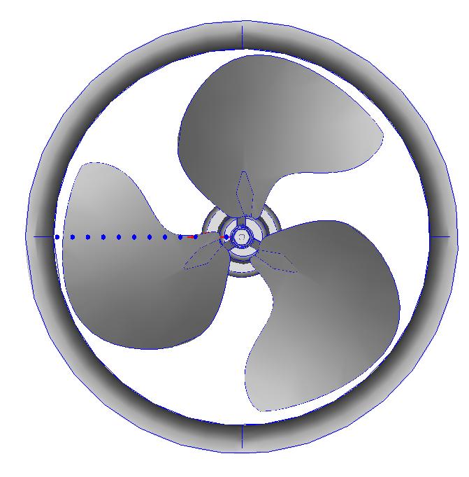
Create the line of monitor points along a Cartesian axis, if possible. This will greatly facilitate determining the radial position of each point. In the example shown above, the points all have the same y and z coordinates, and the origin is at the center of the fan. The radial position of each point is its x coordinate.
If the points are aligned with a Cartesian axis, each velocity component directly corresponds to a component of the fan profile: axial, radial, and swirl. In the example above:
- x coordinate = radius
- x velocity component = radial velocity
- y velocity component = swirl
- z velocity component = axial
If the fan is not centered about the global origin, specify the fan flow direction by selecting a surface on the fan that is normal to the flow direction (instead of selecting a Global coordinate direction). For the radius value of each point in the profile, specify the global coordinate.
After the analysis is complete (so that the velocity values are converged on a time averaged basis), save the velocity components for each monitor point from the Convergence Motor table into an Excel spreadsheet, and save as a “.csv” file.
Rotational Speed
The rotational speed is an optional parameter, and can only be entered as a constant value.
Slip Factor
The slip factor is the ratio of the flow tangential velocity to the rotational speed of the fan blades. Due to inefficiencies in the fan, the tangential velocity of the flow is often slower fan rotational speed. Autodesk® CFD determines the flow tangential velocity by multiplying the slip factor by the specified fan rotational speed. For example, a slip factor of 0.5 results in a tangential flow velocity to be half of the fan blade rotational speed.