Using Surface Parts as Resistances
Surface parts can also be used as distributed resistance regions. Applications include very thin baffles, perforated plates, and any type of very thin obstruction that would be very cumbersome and computationally expensive to model as a volume.
To Assign Distributed Resistance to Surface Parts
On the Materials task, the Resistance material type is available when the Surface selection mode is active.
- Set Surface as the Selection Mode
- Select the surface(s) from the model.
- Click Edit on the Materials context panel, and change the Type to Resistance.
- Select a resistance material from the Name menu or click the Edit button to create one.
- Specify a Shell Thickness.
- Click Apply
The flow direction through a surface part will automatically be normal to the part, so no further directional assignments are necessary.
Cross-flow resistance is automatically set very high so that all flow is aligned normal to the surface.
Unlike volumes, Surface parts cannot be used to simulate pressure drop within the plane of the object (secondary losses). All pressure loss will be in the direction normal to the plane, and the flow will be constrained to be normal to the surface. To allow for secondary-direction flow through a resistance, a volume must be used for the resistance region.
Continuing the Analysis After Changing the Mesh
A nodal reorganization is performed during startup processing to ensure connectivity between the distributed resistance region and the surrounding mesh. This means that it is not possible to change the mesh and continue the analysis from a saved iteration. If the mesh is changed in a model containing a distributed resistance surface part, the analysis must be started back at the beginning (iteration 0).
Geometric Guidelines
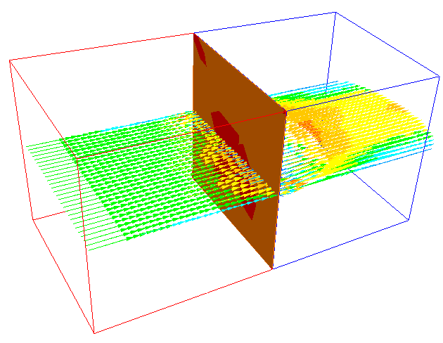
Distributed resistance surface parts are very flexible, and can contact the surrounding wall on one or more edges and even be completely submerged within the fluid:
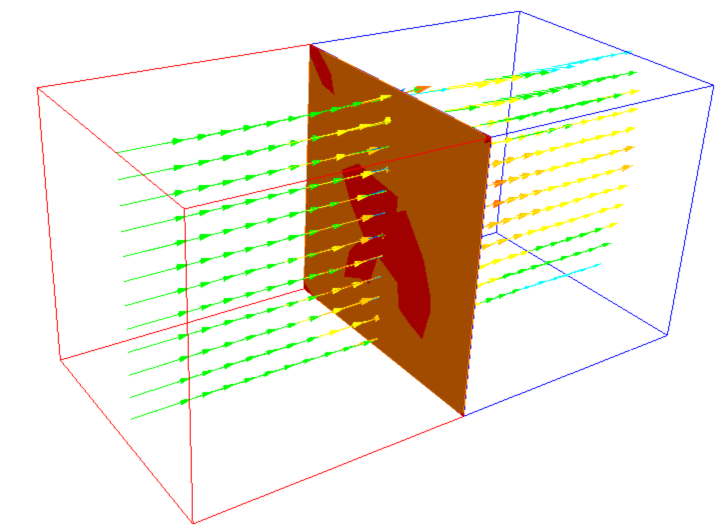
It is very important that the fluid mesh between the edge of a floating resistance surface and the neighboring wall have at least a single row of nodes between them. If no nodes exist in this region, an error will be issued:
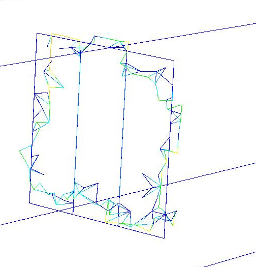
In the following case, the region between the edge of the surface part resistance (in blue) and the wall must have more than one row of nodes.

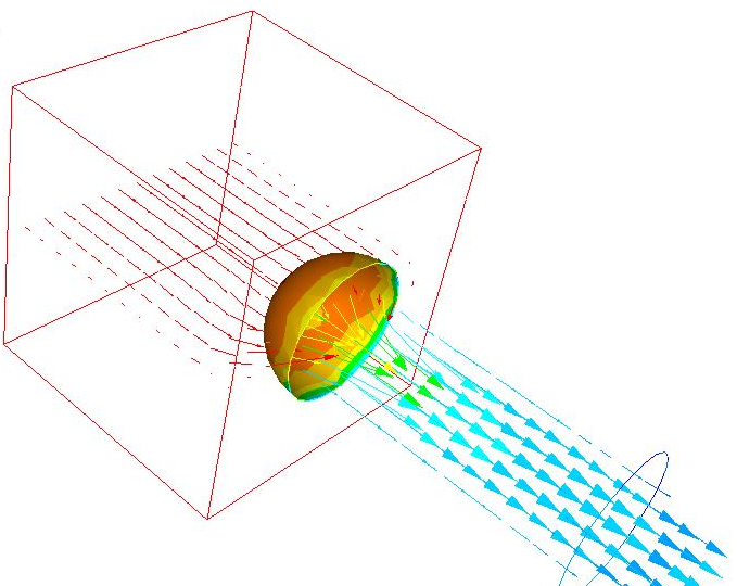
Distributed resistance surface parts can be planar or arbitrarily shaped. The flow direction will always be locally normal to the surface part. Note that there are limitations to the shape of a surface part. Very high curvature surfaces are not suitable for use as distributed resistances, and an error may be given.
Some recommended shapes for resistance surface parts include planes and hemispheres:
An example of an unsuitable surface due to excessive curvature is shown:

Multiple resistance surface parts cannot be joined together to form a “composite” resistance region, and cannot touch other surface parts. A resistance must be composed of a single surface part. Surface parts that share an edge will cause an error in the analysis processing:
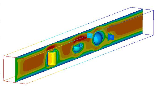
Examples of a baffles modeled with surface parts