Refining the Mesh on Wrapped and Faceted Models
The underlying driver for Automatic Mesh Sizing is the geometry. Mesh is automatically concentrated in regions of high curvature and rapid size variation. In certain situations, significant flow gradients in a simple geometry may require that the mesh be finer than assigned by Automatic Mesh Sizing.
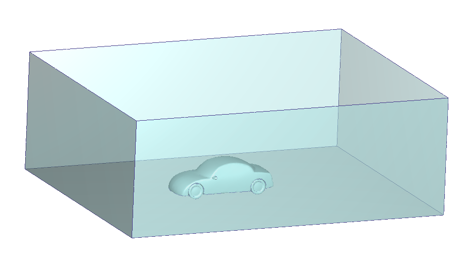
An example is a volume constructed in the wake of an aerodynamics study. The volume is simple, so its automatically-defined mesh will be coarse. Because the flow is quite energetic and will have high gradients, a finer mesh is required in the wake region:
You can use the tools on the Refine tab of the Mesh Settings dialog to control the local mesh distribution on specific parts and surfaces.
Workflow
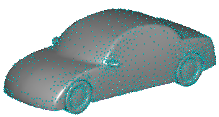
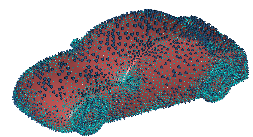
After clicking Autosize to define the mesh distribution on the model, cyan dots appear across the model. These represent an approximate mesh density. They do not indicate actual node locations. You can use these to determine where the mesh will be finer and where it will be coarser. In the following example, the mesh will be finer near the wheels. Along the doors, the mesh will be coarser.
You can use the following procedure to refine the mesh distribution:
1. Select the geometric items to be refined
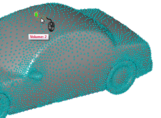
Set the selection type by right clicking off the model, and selecting either Volume or Surface from the Selection list.
Select the items on the model.
2. Adjust sizes with the slider
The slider uses a parametric scale, with a default position of 1.0. This provides a range for decreasing or increasing the mesh size from the original size. To apply a value that exceeds the minimum or maximum slider range, type the scaling value into the field below the slider.
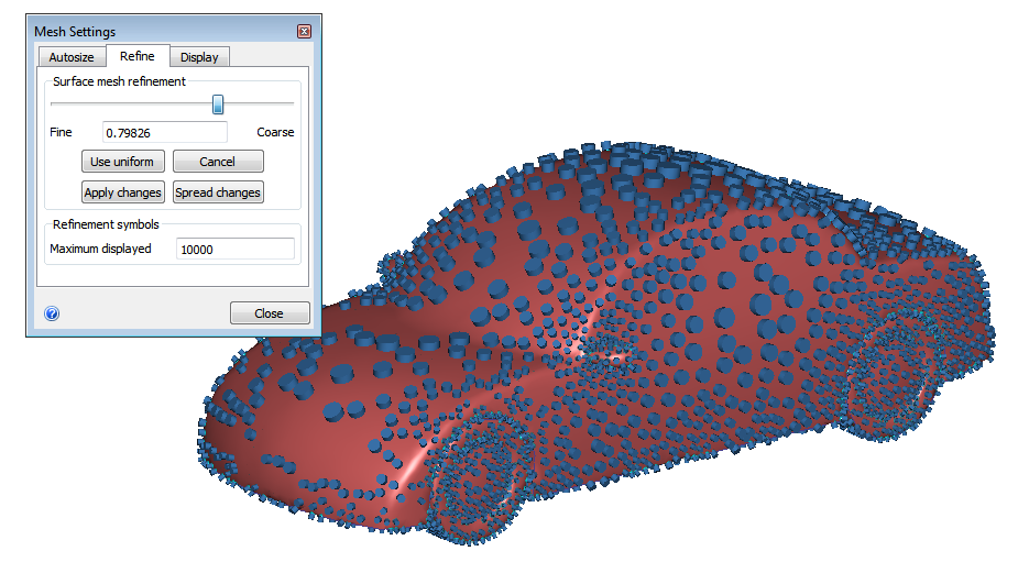
As the slider is moved, the modified distribution updates dynamically. The distribution is indicated by either cylinders or prisms on the displayed on the model. These symbols appear as long as you are left clicked on the slider. When you release the mouse button, the symbols disappear. These symbols represent the size of the elements at specific locations. The width of the symbol shows the element size in the longitudinal direction and the height shows the wall layer thickness into the flow:
To undo the setting and reset the slider to the "1" position, click Cancel. To apply the setting based on the new slider position, click Apply changes.
To preview the element appearance after clicking Apply changes, hover the mouse over the desired location on the model, and hold the Shift key. A prism symbol indicates the approximate element width and height at the current location:
3. Smooth the mesh sizes with Spread Changes
When the Spread Changes button is pushed, all modified settings are resolved with neighboring settings to ensure proper element transitions. The slider position for each adjusted entity resets to 1. This means that the newly assigned size becomes the default size for subsequent adjustments.
In general, the Spread Changes button should be used sparingly because pushing it initiates a complete recalculation of the mesh distribution. If Spread Changes is not pressed prior to leaving the Meshing dialog, the function is invoked automatically when the analysis is started or when the analysis is saved.
4. Optional: Apply Uniform Sizing
Click Use uniform to apply a uniform mesh distribution to a selected entity. This command modifies the underlying length scales throughout the entity to be the same, based on the smallest length scale on the object.
It is not necessarily persistent, however, and subsequent changes to neighboring entities can cause the mesh to vary again. For this reason, it is best to click Use uniform after other adjustments have been made.
Refinement Symbols
As described in section above about modifying the mesh distribution with the slider, symbols appear on the model to indicate the width and height of the elements on the selected objects. By default, only 1000 of these symbols are drawn on the model. If your model is large or complex, increase the number of displayed symbols by changing the value in the Maximum displayed field. Be aware, however, that if you specify too high a value, the visual update/response time of your computer may slow appreciably.
By default, the refinement symbols appear as cylinders. To change them to prisms, click the Display tab, and select Prisms from the Show on model menu.
To Preview the Mesh
To view the mesh prior to generating the mesh:
Select surfaces or volumes.
Right click, and select Preview.
The mesh faces appear on the selected surfaces. Note that if volumes are selected, the element faces appear only on the surfaces of the selected volumes.
To preview the mesh on a single surface (or surfaces of a single volume):
Right click on the surface or volume.
Select Preview.
If a volume is selected, the preview appears on the surface of the volume.
To remove the previewed element faces:
Select the surfaces or volumes that are displayed with a previewed mesh.
Right click, and select Clear.
If the mesh distribution needs to be updated after making certain changes, the preview is not available.
To Delete a mesh distribution
After having autosized and made refinements, you might decide to simply start with defining the mesh distribution. To remove the existing distribution, right click on the Mesh Size branch of the Design Study Bar, and click Remove All. An alternative technique is to right click off the model, and click Remove All.