Diagnostics
The Diagnostics function searches for surfaces that are extremely thin and edges that are extremely small relative to the rest of the model. In many cases, these entities are caused by poor geometry creation practices, a lack of design intent, or are the result of multiple format conversions throughout the life of the design model.
Open the Diagnostics dialog by clicking the Diagnostics button on the Automatic Sizing context panel (or on the Mesh Sizes quick edit dialog).
The controls for surface and edge modes perform different actions, but are designed to help identify problems and/or simplify the analysis model.
Edge Mode Diagnostics
Edge Mode Diagnostics locates edges that are extremely small relative to other edges in the geometry. Variations in edge length greater than several orders of magnitude are often indicative of a geometric problem which may cause difficulty for the mesher. The distribution of edge length values throughout the model is also calculated, and is then used to determine the “Minimum Refinement Length” as used by the mesher.
The Minimum Refinement Length is the threshold edge size that will be allowed to influence the mesh in neighboring features. Edges that are below this size will be meshed, but will only have a node at each end. Such small edges are meshed with a single small element, but that small element size will not propagate to other features in the model.
The Edge Mode dialog provides two mechanisms for dealing with extremely small edges: Small Edge Identification and Adjustment of the Minimum Refinement Length.
Small Edge Identification
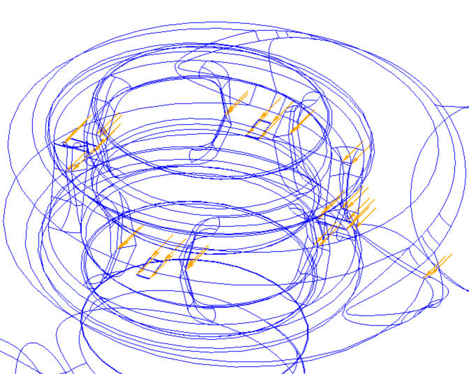
When the model is first opened, all edges that are three orders of magnitude or more smaller than the largest edge in the model are identified, and the slider can be used to vary the highlighted size.
A default Minimum Refinement Length is automatically determined based on relative edge lengths throughout the model. This value is shown in the Min Refinement Length field in the dialog, and is the default slider position. When the slider is at this position, all highlighted edges fall below this value, and will only be meshed with two nodes.
If a large number of edges are smaller than the Minimum Refinement Length, it may be necessary to reduce its value. In such cases, the Mesh task dialog will open directly to the Edge Diagnostic panel, and many edges will be marked with arrows. Reducing the Minimum Refinement Length will improve the chances of successfully generating a mesh.
Edges that are the current size indicated by the slider and smaller are highlighted.
If no edges are less than three orders of magnitude smaller, then the slider will be grayed out.
Adjustment of the Minimum Refinement Length
The Minimum Refinement Length provides control over whether (and to what extent) smaller length scales propagate throughout the mesh. This feature does not remove small features, but can limit their effect upon local length and mesh scales.
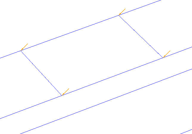
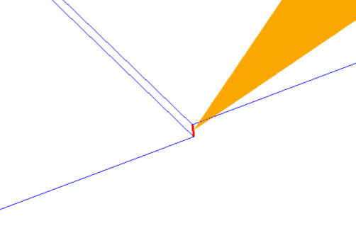
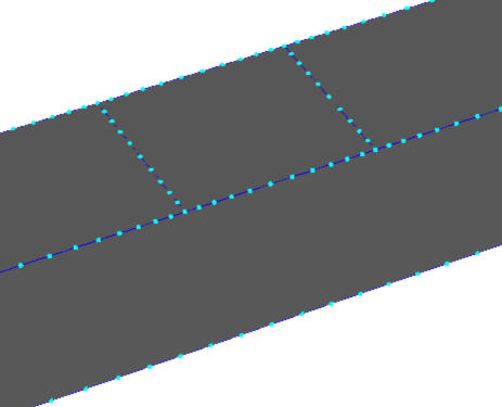
As an example, the model shown has four very small edges at the corners of the cut-out. Each edge is highlighted, and is identified with an arrow:
This improves the mesh on very small features, but may increase the number of nodes and elements in your analysis model. This is necessary if important edges fall below the default Minimum Refinement Length.
In the following image, the Minimum Refinement Length is set to be smaller than the length of the four small edges. Note their effect on the mesh:
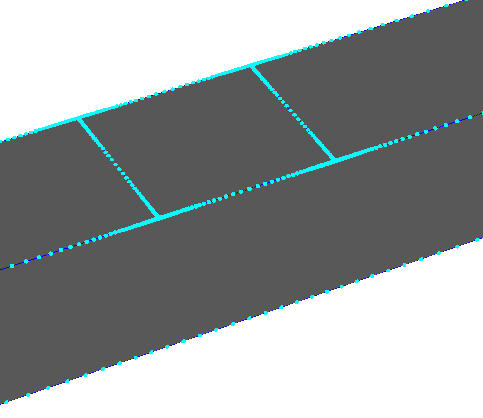
Edges that are longer than the default Minimum Refinement Length are meshed finer, and affect neighboring geometry.
Edges that are shorter than the default Minimum Refinement Length are meshed coarsely, and do not affect neighboring geometry.
In the image below, the Minimum Refinement Length is set to be larger than the small edges. The mesh distribution will be considerably more coarse. The edges will be meshed, but will not strongly affect the mesh on surrounding geometry:
Changes to the Minimum Refinement Length affect the model globally, and are not isolated to a particular location. Care must be taken so that the Minimum Refinement Length is not accidently made larger than other important edges elsewhere in the model. Doing so will effectively remove their influence on the mesh, and may lead to accuracy issues.
Note that if the Minimum Refinement Length is changed after applying Automatic Mesh Sizing, the mesh distribution must be reapplied by clicking the Automatic Size button. Otherwise, the new Minimum Refinement Length will not affect the mesh distribution.
Edge Diagnostics Process
When the CAD model is first loaded, all edges are scanned and a Minimum Refinement Length is determined. If any edges are shorter than this length, the controls in the dialog are active, and the edges are highlighted.
The Status group indicates that edges three orders of magnitude smaller than the longest edge exist with the message “Potential Problems Found.” The Arrows check box toggles arrows that point to all small edges to help locate them.
Use the Highlight Edges slider to vary the edge length. Move to the left to reduce the length; the far left position shows the smallest edge in the model.
Change the maximum displayed edge length by keying a new value in the Max Size field. This is useful for showing more edges. Restore the default value with the Restore Default Max button.
Save the displayed edges to an external text file with the Save to a Text File button. The text file containing edges will be automatically named: analysisname-edges.txt.
Add the displayed edges to a group with the Save to a Group button.
If necessary, change the Minimum Refinement Length by either keying in a new value or by clicking the Use Highlight Length button. The default value can be restored with the Restore Minimum Length Scale button.
Surface Mode Diagnostics
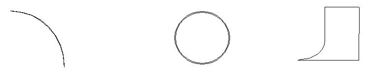
Surface mode Diagnostics identifies potentially problematic surfaces that may lead to meshing difficulties. Examples of such surfaces include slivers (left), very thin annular surfaces (middle), and surfaces with a “cusp” or tangency region (right):
Surfaces are deemed “problematic” based on the separation distance between edges. The variation of separation distances is assessed to determine a minimum threshold. All surfaces with an edge separation distance below this threshold are considered potentially problematic, and are shaded.
Extremely high-aspect ratio surfaces such as slivers and annuli have edges that are very close to each other within the separation distance. Surfaces that contain tangencies may be mostly well formed, but can be considered problematic because of the tangency between two or more edges.
Problematic surfaces have been the reason for many meshing failures or solution problems due to a badly distorted mesh. Identifying and locating them before attempting to run the analysis is essential to reducing wasted time and effort. This dialog provides two ways of dealing with problematic surfaces: identification and refinement.
Identification
The first function, identification, is performed by coloring the surfaces orange. Use the slider on the dialog to vary the edge separation distance from the threshold to the minimum.
When the slider is moved to the left, the display is restricted to progressively smaller surfaces until the far left position--which shows the very smallest surface or surfaces. Displayed problematic surfaces can then be added to a group and saved to an external text file for reference.
The text file makes it convenient to locate the surfaces in the CAD model and apply a fix.
An example of the data in the output file is shown:
distance: 0.05842
min coordinates: 0 0.02921 -0.05842
max coordinates: 0.00152 0.02921 0
- In line 1, the distance is the maximum sphere diameter that will fit between the confines of the surface edges. This is approximate and not derived by the CAD kernel. Use this information to identify surfaces that are significantly smaller than surrounding surfaces. Sliver surfaces are an example of such surfaces.
- In lines 2 and 3, the coordinates are the bounding box coordinates for the individual surface. Use this data to locate problematic surfaces in the CAD tool.
- This data is always in the original units of the model, and are not affected by unit conversions applied in Autodesk® CFD.
Keep in mind that the principal objective of Surface Diagnostics is to locate the smallest surfaces in the model. Such surfaces are often unintentional that will make meshing difficult or impossible.
However, there are situations in which small surfaces are intentional, and cannot be removed.
In some cases, surfaces may be identified that are simply the smallest surface in the model, without having any inherent flaw. They will likely be ignored by the Automatic Refinement.
In other cases, very small surfaces are identified that are truly high aspect- ratio slivers, and will be refined automatically to ensure the successful creation of a quality mesh.
Refinement
The second function is Automatic Refinement. This is an attribute that is assigned to high aspect-ratio surfaces that causes them to be refined automatically by the Automatic Mesh Sizing facility. This is used primarily for surfaces that fit the following criteria:
- Very high aspect-ratio (longer and thin)
- Close proximity to larger surfaces
This function is fully automatic, and only affects high aspect-ratio surfaces. Its purpose is to ensure that such surfaces are meshed finely enough so that the specified mesh sizes do not significantly exceed the dimensions of the surface. These reduced length scales are then propagated to the surrounding entities, resulting in a smooth transition.
After Automatic Mesh sizing has occurred, surfaces that will be automatically refined are shaded in an olive color.
Extreme transitions have been found to have a detrimental effect on both the generation of the mesh as well as the solution accuracy.
Surface Diagnostics Process
When the CAD model is first read into Autodesk® CFD, the geometry is scanned and problematic surfaces are identified. If found, the controls in the dialog are available to identify and store them to a text file or group:
- The Status group indicates if any problem surfaces are found. Only problem surfaces are then displayed, and are colored orange for clarity. These surfaces are considered for automatic refinement.
The Arrows check box toggles arrows that point to the small surfaces.
Use the Highlight Surfaces slider to vary the edge separation distance. Moving to the left reduces the separation distance, and shows the smallest surfaces.
Change the displayed maximum edge separation by keying a new value in the Max Size field. This is useful for showing more surfaces. Restore the default value with the Restore Default Max button.
Save the displayed surfaces to an external text file with the Save to a Text File button.
- Add surfaces identified as problematic to a group with the Save to a Group button.