By default, there are three general shape symbols and three exceptions for fillet welds. You can modify the existing shape symbols or you can create a new exception for a desired weld type.
In this example, a surface shape symbol for a "Y" weld type will be created.
To create a new surface shape symbol exception for a "Y" weld type, follow these steps:
- Open the "WeldTemplate.dwg" located in ...\ProgramData\Autodesk\Advance Steel 2024\[INSTALLATION LANGUAGE EXTENSION]\Shared\Support\Symbols
Important: It is strongly recommended that you modify the "WeldTemplate.dwg" in plain AutoCAD®. Make sure that Advance Steel is not loaded.
- Open the Layer Manager.
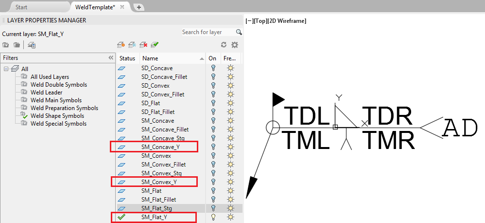
- The layer name must contain the following:
- "SM_" (or "SD_") prefix.
- Surface shape name: Flat, Convex, Concave.
- A suffix (could be any suffix but it is recommended to use the name of the weld symbol as suffix, for example "_Y").
The layer name should look like this: "SM_Flat_Y".
Repeat steps 2 and 3 for Convex and Concave surface shape symbols.
 Note: Starting with Advance Steel 2016, each weld symbol has its own layer.
"WM_","WD_", "SM_","SD_","PM_","PD_" are acronyms for Weld Main, Shape Main, Preparation Main etc, and are not mandatory but are recommended for organizational purposes.
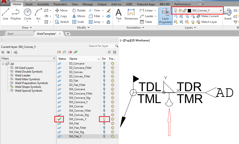
- Turn off all the other layers associated with surface shape symbols.
- Turn on the new layer and set it as the current layer.
- Draw the desired symbol (be sure to draw on the correct layer).

- Repeat steps 2, 3 , 4, 5 and 6 for the weld double surface shape symbol.
- Once the drawing process is done, save and close the "WeldTemplate.dwg".
- Start Advance Steel and access the Advance Management Tools.
- In the Advance Management Tools, start the "Table editor" application.
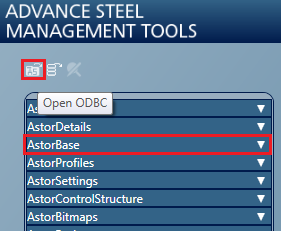
- Click the Open ODBC icon and select AstorBase.

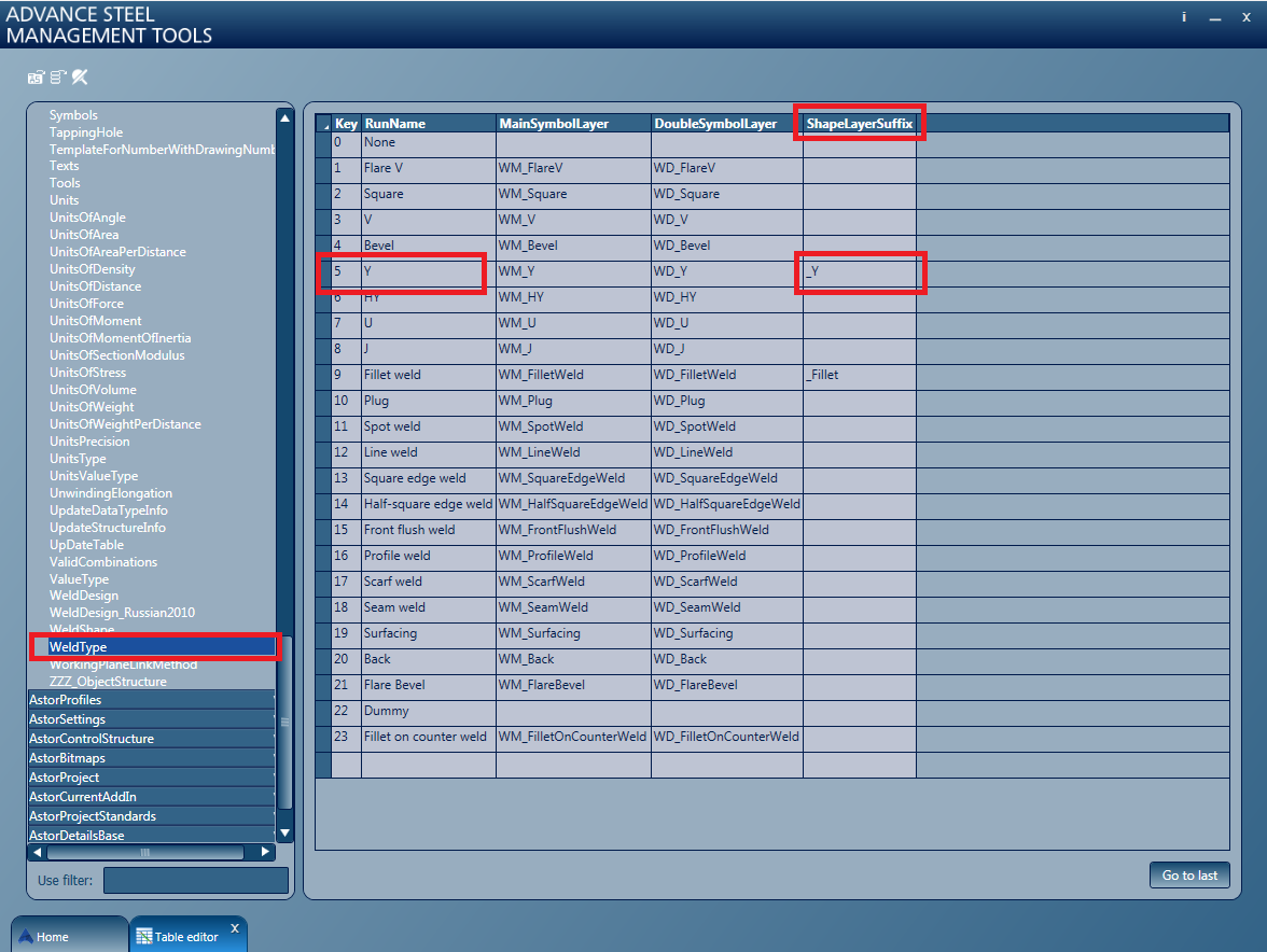
- Open the "WeldType" table.
- Search for the weld type for which the surface shape was drawn (for example, "Y").
- Fill in the ShapeLayerSuffix column with the suffix used in step 3. ("_Y").
