Learn how to make a generic configuration to a drawing with basic changes to its overall settings and how to modify the way objects are detailed and labeled.
- Creating drawing style copies that still use shared components with other drawing styles (to avoid the Copy of items that appear when using Deep Copy).
- Explaining the position relative to the drawing style structure of all generic settings associated to a drawing style.
- How to control the way objects are detailed - line-type, color, etc.
- Changing the automatic labeling strategy.
The example is based on the following requirement: Objects that have a different role in the model should be printed with a different line-type, and also have a different labeling strategy.
- Detail the different objects using different colors - this is setup using the drawing style.
- Plot the different colors using a specific line type (e.g. zigzag, hidden, or dashed) - this is setup using the plotting .ctb file.
Using this workflow it is possible to plot two beams detailed as visible, but with different structural roles and with two different line types. This configuration does not apply to the DWG file (where the difference is only the used color). The configuration applies when sending to any type of plotting (PDF, paper), the CTB file will control the line type.
Step 1: Assign a different line color to each different object type for which you need to control the plotted line type.
Sample model and drawing style: an elevation view on a support beam and a railing.
- The beam has the Beam model role.
- The railing has the Railing Handrail Landing model role.
- The drawing style used for this sample is 3-Elevation View - Line, from the U.S. Installation (Advance Steel 2017).
- Open the Drawing Style Manager, browse to the 3-Elevation View - Line drawing style and access the Objects presentation view tab.
- A common drawing style will not have specific filters for dedicated model roles. Most of the beam elements are detailed using a common rule - Beams, with other specific roles being either ruled out or controlled by dedicated rules. In this example, for the two model roles, two new rules need to be added in the list: one for the beams with the Beam model role and another for the top handrail.
-
Add a new rule: when adding a new object presentation to an existing drawing style, the style itself is modified. At this point you can either change the default style - but you might risk changing another drawing style that uses the same shared settings, or you can create a copy of the necessary settings, and obtain a new drawing style that still shares settings with other styles, but has individual settings specifically targeting the areas of interest. In this example, a new drawing style is created, and the shared settings that need to be cloned are the view and the object presentation.
- Create a coy of the drawing style using the Copy command from the right-click contextual menu.
- Access the view properties of the copied drawing style and use the
 (New) button from the View definition tab to create a new view.
- Access the Object presentation category of te new view and create a new presentation rule, using the
 (New) button from the Object presentation tab.
- Once this step is done, you have a new drawing style that uses a new view, with a new object presentation and any changes made to this object presentation will not affect any other existing drawing styles.
- Add two new object presentations, using the
 (Add a new object presentation) button in the Object presentation tab. The two new rules will be added to the end of the list and they will be a duplicate of the first rule - will be changed as part of this configuration.
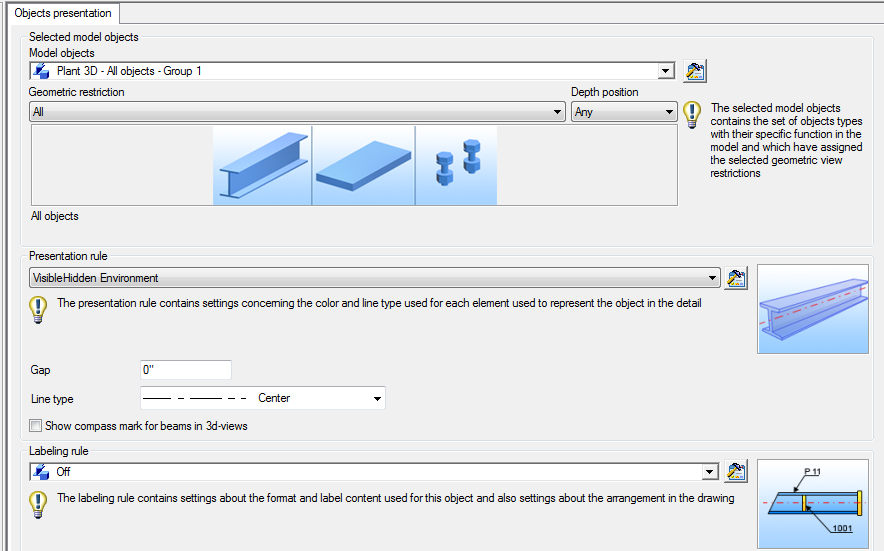
- Configure the object presentation to match the requirements. Double-click on the line to go to the more advanced view of the configuration.
-
Model object: This option will control what object from your model will be detailed by this specific line. Part of this configuration is to match specific model roles - those model objects need to be selected to match the object type (beam, plate, etc) and the model role. Search through the list and select the required model role. The out-of-the-box Advance Steel provides a wide series of pre-configured model objects. The model object for beams with the Beam model role exists and it is named Mp - Beam (model role).
Note: Mp is short for Main part, so this model role will also act as a filter for main parts in assemblies. If a required pre-configured model object does not exist, it can be added. For example, the model object for the Railing Handrail Landing model role is not available, so it needs to be added as follows:
- Use the
 (Set) button next to the Model object category to access the configuration page.
- Create a new model object using the
 (New) button.
- Configure the Model object and Model role fields as needed.
- Use the
- Presentation rule: Set both the new object presentation rules on SingleLine.
- Set a labeling rule if needed.
-
- Once you finish the previous steps, you obtain two new object presentation rules for the two model roles, both with a SingleLine object presentation:

The SingleLine object presentation will detail both elements using a single line, with the default red color.
In order to control the color of the two rules, you need two new object presentation rules, based on the SingleLIne rule - but using different colors.
- Access the presentation rule for the first object (for Beam - Railing Handrail Landing (model role) and use the
 (Set) button for the Presentation rule category to open the Presentation configuration panel. The default SingleLine presentation, found in the out-of-the-box installation, is configured with the Single line element set on the default color - which means Advance Steel will use the color set in the Management Tools defaults for Single Line objects.
- Create a new presentation rule using the
 (New) button.
- Expand the Color column combo-box for the Single line element and select a different color (e.g. Green).
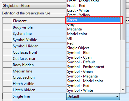
- Repeat the steps for the other model object (Mp - Beams (model role) and create another Single line presentation rule, with a different color.
- Once the two object presentations are added, they need to be positioned in a way that Advance Steel will prioritize them when detailing the objects. This is required because the software details objects starting from number one, going downwards in the object presentation list.
Once an object is detailed by a line, then it will not be detailed by other lines after it - even if the rule matches the object. For example, if at position 20 you have a rule detailing all beams, regardless of their numbering type or model role, then the rule we configured at position 40 to detail the beams with the Beams model role and a blue single line will be ignored. However, if you move the new rule ahead of the 20th line, then Advance Steel will detail all beams with the model role Beams, using the dedicated presentation rule, and when it reaches position 20 it will detail the rest of the beams (that don't have the Beam model role) with the respective object presentation.
In this case, the two new object presentations should be moved at positions 3 and 4.
Detailing this small sample model with this drawing style will result in a drawing with two lines: a green line for the Railing Handrail beam, and a blue line for the beam: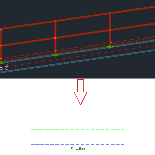
Step 2: Use the line color to control the plotting line type, through the AutoCAD plot CTB configuration file
When plotting an Advance Steel drawing using the AutoCAD plot functionality, the way each line is plotted is controlled independently from the way the drawing looks when it is open in Advance Steel through the CTB file - a plotter assigned set of rules, which can be edited, saved and reused as needed.
Advance Steel comes with a default ctb file called AdvanceSteel.ctb, found in...\ProgramData\Autodesk\Advance Steel 2024\[INSTALLATION LANGUAGE EXTENSION]\Shared\Support\
Change the plotting strategy
- Open the Plot Setup Manager dialog by right-clicking on the ANSI Advance Steel layout and choosing the Plot Setup Manager option.
- Use Modify button in the Page Setup Manager dialog to access the page setup dialog.
- The page setup dialog provides the option to control the way the current drawing is plotted; this setting is saved per DWG file. This can also be done directly in the prototype (using the same steps to access the Page Setup dialog), allowing Advance Steel to produce all the drawings using the same settings.
- Select AdvanceSteel.ctb from the combo-box on the top-right side and access the Edit page by clicking the button next to the combo-box.
- The Plot Style Table Editor dialog offers the option to map the color of various lines on the drawing, with the way they are plotted.
On the left side of the dialog, under Plot styles, all the colors that can be assigned are listed. New colors from the DWG can be detected as well, if used.
On the right side there are the properties of how the respective color line will be plotted. By default, almost all the colors are configured to be plotted with the Linetype set on Use object linetype - so the linetype will be read from the DWG, but if needed, the linetype can be controlled and a dashed single line from the drawing can be plotted with a continuous line, for example.
Add more color values to the object presentation configuration table
You can add more color values to the object presentation rule configuration, by editing a database as follows:
- Open the Management Tools application and access the Table editor.
- Use the top-left button to load the databases.
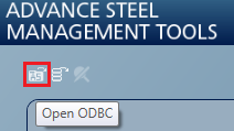
- Browse to the AstorDetailsBase database and open the DetAcadSettings table.
- Scroll to the end of the table, and add a new line with the following values:
- Key - this requires a unique number - preferably a value that is consecutive to the last entered one.
- RunName - the name of the color. This value will appear in the Drawing Style Manager, when editing the Object Presentation rule.
- Color - the value associated to the required color. The table supports color codes from 1 to 256. To easily find the number associated to each color:
- In the Management Tools application, access Defaults.
- Browse to any category that contains defaults which set a color (e.g. Drawing-Presentation / Colors).
- Click on the property value of any default to see the color table. Hover the mouse over various colors and check their index color value:
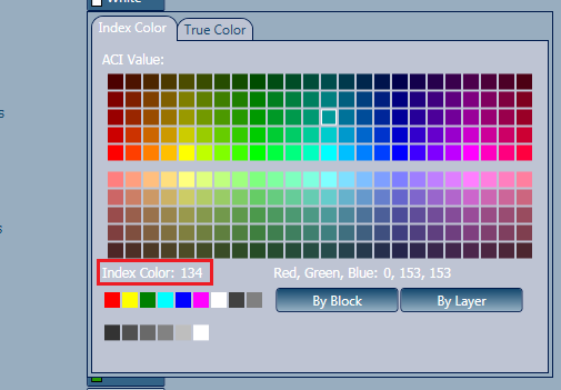
- Leave the Layer and Linetype fields empty.
- OwnerText: use the current Author/Owner value from the combo-box.
After making the modifications, make sure to restart Advance Steel for the settings to apply in the Drawing Style Manager.
Change the labeling strategy for the two new lines
In the object presentation page, for each line associated to a model object - the filter that has the role to detail a specific object from the model - with an object presentation - the style, line-type and color used by Advance Steel to detail the object, there is also a column that can be associated to a labeling strategy.
The labeling strategy handles the rules that Advance Steel uses to create a label on the respective object, with the content of the label using real information about the object, the graphic appearance and the orientation/positioning on the drawing.
You can assign a labeling strategy using the combo-box available when clicking on the cell. Advance Steel comes with a large variety of preconfigured labeling strategies that can be reused at any point.
Because at the previous step, a new object presentation rule was created, changing and reusing existing labeling strategies will not affect any existing drawing style configurations and it will only apply to the newly configured drawing style.
Modify or create a new labeling strategy
It is often required to make small modifications to existing labeling strategies, or create new ones. For any required modification, you need to follow a certain number of steps to ensure that the change is well recognized and used only where it is intended. As the labeling strategies are shared, making a modification to one of them will transfer to any other drawing style that uses the respective labeling strategy. Because of this, there are two scenarios:
- "I want to modify all my labeling strategies for this specific label, because I use a different font for my label text."
In this case, the shared functionality of Advance Steel labeling strategies is very efficient, as the change in font type can be done only once - and automatically transferred and used by any drawing style.
- Open Drawing Style Manager and access the Labeling strategies tab.
- Make any modification regarding the labeling strategy to any of the items in the list.
Note: In this view, the Drawing Style Manager will NOT display in which drawing style those strategies are used.
- " I need to modify or create a new labeling strategy that I will use only for a specific drawing style."
For this case, a new labeling strategy needs to be created. The labeling strategy tab is split into two parts - so depending on which part needs to be modified, the workflow is different:
The first half of the page contains generic information about the leader line, text direction and orientation. These settings are part of the labeling strategy itself, and are not connected to the content of the label.
Create a new labeling strategy by using the
 (New) button.
Once created, use drag and drop (click it, hold the left mouse button and move) to move the newly created labeling strategy to a different category, if needed.
The second half the page contains the label content settings. These settings are also shared, so you can have a different labeling strategy using the same content rule. Therefore, if the change is needed here, you need to:- Create a new labeling strategy as mentioned in the previous step (even if no modifications are required).
- Create a new label content rule.
Create a new label content rule, using the
 (New) button
The content of label rules does not have categories; the label rules will be listed in the combo-box alphabetically.
Set the Used for object option according to the object where the label will be used. There is an All Object setting as well for a more generic rule.
Make the content configuration change according to the requirements, using the label editor - change the label format, use tokens to display updated information about the object parameters, format the text.
Label arrangement rules
The last point on the label strategy page is the label arrangement. This is separated from the label content, and it's under the label strategy - so when a change is needed only for this part, the label strategy needs to be copied as described at the first point.