A Face window is where you define geometry (when in CAD mode) or groups of part features, such as holes and profiles (when in CAM mode) that need to be machined.
You can view the Face windows and any groups of part features programmed in those Face windows in the Job Explorer pane.
Use the CAD/CAM Switch in the bottom left of the Face window to switch between CAD and CAM modes:
 indicates you are in CAD mode and
 indicates that you are in CAM mode.
Icons
Using the icons on the left side of a Face window you can specify new hole locations and create new profiles. One icon is always selected to indicate the current mode.
Milling icons

 Zero icon — Use this icon to define a new part origin using
snap modes.
Zero icon — Use this icon to define a new part origin using
snap modes.


 2-Point Chain icon — Use this icon to define a profile by selecting its start and end points on a contiguous piece of geometry.
This icon appears in the following PartMaker face windows:
- Turn
- Mill XY Plane
- Mill 5 Axis Plane
- Mill ZY Plane
- Mill ZX Plane
- Mill Polygon
- Mill End, Polar
- Mill Diam, Polar
- Mill Cylinder
- WireEDM

 Define Profile icon — Use this icon to create a profile using
snap modes. This icon is available only if a profile group already exists and is selected.
Define Profile icon — Use this icon to create a profile using
snap modes. This icon is available only if a profile group already exists and is selected.
This icon is displayed in the following PartMaker faces:
- Turn
- Mill ZX Plane
 Chain Geometry icon — Use this icon to define a profile, by selecting an end point of a line or an arc.
PartMaker automatically finds all connected lines and arcs.
Chain Geometry icon — Use this icon to define a profile, by selecting an end point of a line or an arc.
PartMaker automatically finds all connected lines and arcs.
This icon is displayed in the following PartMaker faces:
- Mill ZX Plane
- Turn
 Define Profile icon — Use this icon to create a profile using
snap modes. This icon is available only if a profile group already exists and is selected.
Define Profile icon — Use this icon to create a profile using
snap modes. This icon is available only if a profile group already exists and is selected.
This icon is displayed in the following PartMaker faces:
- Mill End, Index
- Mill Diam, Index
 Chain Geometry icon — Use this icon to define a profile, by selecting an end point of a line or an arc.
PartMaker automatically finds all connected lines and arcs.
Chain Geometry icon — Use this icon to define a profile, by selecting an end point of a line or an arc.
PartMaker automatically finds all connected lines and arcs.
This icon is displayed in the following PartMaker faces:
- Mill End, Index
- Mill Diam, Index
 Hole Pattern icon —
The
Hole Pattern Icon is not displayed if the
Hide Hole Patterns Icons option is selected in the
Preferences dialog.
Hole Pattern icon —
The
Hole Pattern Icon is not displayed if the
Hide Hole Patterns Icons option is selected in the
Preferences dialog.
- In PartMaker/Mill, clicking this icon displays a context menu.
Solid model icons for programming on solids
 Single Hole on Solid Model Icon — Use this icon to create holes by selecting a single hole surface from a solid model that has been imported into
PartMaker:
Single Hole on Solid Model Icon — Use this icon to create holes by selecting a single hole surface from a solid model that has been imported into
PartMaker:
- Make sure you have imported a solid model into PartMaker.
- Click
.
- Move the mouse over the solid model. PartMaker highlights any surface on the solid model that belongs to a valid hole.
- Click to select a hole surface. PartMaker creates a new Hole Group with locations that correspond to the selected hole surface.
This icon is displayed in the following PartMaker faces:
- Mill XY Plane
- Mill 5 Axis Plane
- Mill ZY Plane
- Mill End, Index
- Mill Diam, Index
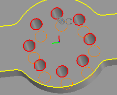
 Chain Holes on Solid Model Icon — Use this icon to select a group of identical hole surfaces on a solid model and create hole features for each hole selected.
As you move the mouse over the solid model to select a hole, PartMaker automatically selects that hole together with any other holes that have identical features. For example:
This icon is displayed in the following PartMaker faces:
- Mill XY Plane
- Mill 5 Axis Plane
- Mill ZY Plane
- Mill End, Index
- Mill Diam, Index
 Define Profile on Solid Model icon — Use this icon to create a profile on the imported solid model using available
Solids snap modes. This functionality is available only if a profile group, or a surface group, already exists and is selected.
Define Profile on Solid Model icon — Use this icon to create a profile on the imported solid model using available
Solids snap modes. This functionality is available only if a profile group, or a surface group, already exists and is selected.
This icon is displayed in the following PartMaker faces:
- Mill XY Plane
- Mill 5 Axis Plane
- Mill ZY Plane
- Mill Polygon
- Mill End, Polar
- Mill Diam, Polar
- Mill Cylinder
 Chain Geometry on Solid Model icon — The Chain Geometry on solid Model icon allows the user to define a profile on the solid model by chaining a group of edges by selecting:
- The beginning vertex and direction of chain, and
- The end vertex of the chain.
The software initially attempts to chain edges in the face plane. If chain creation fails, then an attempt is made to chain all tangential edges beginning with the user-selected vertex and chaining direction. Tangential chaining is only available when the Select Edges in Face Plane Only parameter in the Solids Options dialog is turned off.
This icon is displayed in the following PartMaker Faces:
- Mill XY Plane
- Mill 5 Axis Plane
- Mill ZY Plane
- Mill Polygon
- Mill End, Polar
- Mill Diam, Polar
- Mill Cylinder
 Define Profile on Solid Model icon — Use this icon to create a profile on the imported solid model using available
Solids snap modes. This functionality is available only if a profile group, or a surface group, already exists and is selected.
Define Profile on Solid Model icon — Use this icon to create a profile on the imported solid model using available
Solids snap modes. This functionality is available only if a profile group, or a surface group, already exists and is selected.
This icon is displayed in the following PartMaker faces:
- Mill ZX Plane
 Chain Geometry on Solid Model icon — This icon allows you to define a profile on the solid model by chaining a group of edges by selecting :
- The beginning vertex and direction of chain, and
- The end vertex of the chain.
The software initially attempts to chain edges in the face plane. If chain creation fails, then an attempt is made to chain all tangential edges beginning with the user-selected vertex and chaining direction. Tangential chaining is only available when the Select Edges in Face Plane Only parameter in the Solids Options dialog is turned off.
This icon is displayed in the following PartMaker Faces:
- Turn
- Mill ZX Plane
 Define Profile on Solid Model icon — Use this icon to create a profile on the imported solid model using available
Solids snap modes. This icon is available only if a profile group, or a surface group, already exists and is selected.
Define Profile on Solid Model icon — Use this icon to create a profile on the imported solid model using available
Solids snap modes. This icon is available only if a profile group, or a surface group, already exists and is selected.
This icon is displayed in the following PartMaker faces:
- Mill End, Index
- Mill Diam, Index
 Chain Geometry on Solid Model icon — This icon allows you to define a profile on the solid model by chaining a group of edges by selecting:
- The beginning vertex and direction of chain, and
- The end vertex of the chain.
The software initially attempts to chain edges in the face plane. If chain creation fails, then an attempt is made to chain all tangential edges beginning with the user-selected vertex and chaining direction. Tangential chaining is only available when the Select Edges in Face Plane Only parameter in the Solids Options dialog is turned off.
This icon is displayed in the following PartMaker Faces:
- Mill End, Index
- Mill Diam, Index
Layout icons
 Split Screen icon — Click this icon to split the display, so that the Face window and the Solids window take up an equal amount of space. This icon is displayed only when a solid model is loaded.
 Maximize Solids Window icon — Click this icon to maximize the Solids window. This icon is displayed only when a solid model is loaded.
 Minimize Solids Window icon — Click this icon to minimize the Solids window. This icon is displayed only when a solid model is loaded.
Color Palette
In CAM mode, use the Color Palette change the color of a group:
- Select a group in the Job Explorer pane.
- Click a color in the Color Palette to make it the sample color:
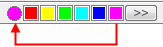
To display more colors, click >> to display the Color dialog.
- Click the sample color. PartMaker changes the color of the group to the sample color.
Displaying the axes
You can display the axes in a face window by selecting View > Show Axes.
Displaying the grid
You can display the grid in a face window by choosing View > Show Grid.
Displaying the boundaries
You can display the boundaries in a face window by choosing View > Show Boundaries.
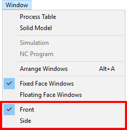
Displaying different Face windows
When you have multiple CAM Face windows, you can quickly switch between them by selecting the name of the Face window you want to display from the Window menu. For example: