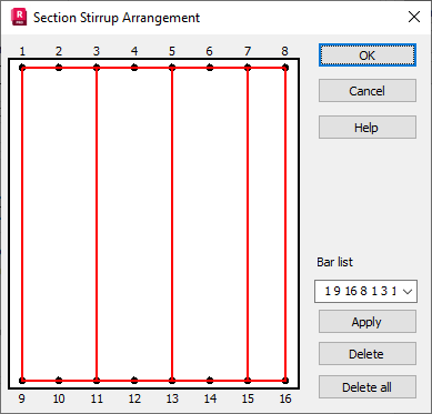
This option is used for a manual definition of a shape of the beam transversal reinforcement (at the section level).
The option is available in the Reinforcement Pattern (beams) dialog box - the Transversal Reinforcement tab. When the option is selected a dialog box shown below will appear on the screen.

The condition for the activity and correctness of the option operation is defining the same Nmin and Nmax reinforcement column number in the Main reinforcement parameters dialog box on the General tab. When the Nmix = Nmax is set on the Transversal Reinforcement (the Section field), the AUTO option is active. If the Auto option is not active and the User Definition button is pressed, the above dialog box with a general view of a beam section, where the longitudinal reinforcement is displayed, appears on the screen.
To define the transversal reinforcement shape and arrangement, one should click in the consecutive longitudinal bars; the transversal reinforcement shape is defined in this way. The determined shapes should be closed figures for stirrups. The symbol for a pin or a shackle is a straight segment connecting two longitudinal bars. The consecutive shape definitions should be ended by pressing the Apply button.
The defined shape can be seen on the section.
When the error occurs during the definition there is the possibility to come back to the previous defined shape. The demanded shape should be selected and then deleted by the developed list of defined shapes.
Pressing the Delete All button results in deleting all defined stirrup shapes.