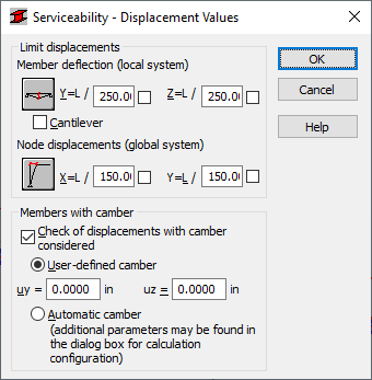
Use this option to define additional code-governed parameters for the values of displacements (limit displacements). Acces the option by clicking the Service button located in theMember Definition - Parameters dialog. The following dialog displays:

Use the dialog to define limit displacements (member deflections and node displacements) and to specify if the bar is a cantilever. You can define:
- Member deflection: Y and Z. Use the Y and Z fields to define limit deflection of a bar in the direction of axis Y and Z, respectively, depending on the length of the bar, e.g. L/200.
- Node displacements: X and Y. Use the X and Y fields to define limit displacement of a bar node in the direction of axis X and Y, respectively, depending on the length of the bar, e.g. L/200.
The lower part of the dialog is used to define parameters of a member with initial deflection.
- If the Control of displacements with initial deflection consideredoption is selected, then, the value of the initial deflection is considered during verification / design of bars.
- The value of initial deflection is determined in two ways: by typing the value of this deflection in the User's initial deflection field, or by assuming the value calculated on the basis of constant loads (the Initial deflection - automatic option).