Using this option, you can determine the orientation of planar finite elements in space (Change of local Z axis sense). After defining a panel, you can also define the sense of the normal to that panel (sense of the Z axis of the local coordinate system). Access the option by:
- clicking Geometry menu > Properties > Local Panel Direction.
- clicking
 on the toolbar.
After the option is selected, the Local System Orientation dialog displays.

You can determine a direction of the local x axis assigned to a panel. The Cartesian or Polar system may be assigned to each of the panels.
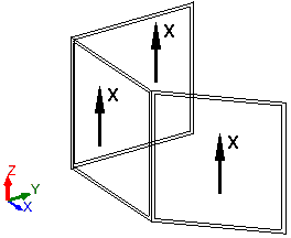
When you select Cartesian and Definition of local X axis direction, you can also specify the direction vector of the X axis. You specify vector coordinates defining the direction and sense of the local X axis of a panel (for example, the vector (0 , 0 , 1) may be a direction vector). The following image displays the direction vector of the X axis for several walls. Separators in the vector definition are the separators specified in the Microsoft® Windows system (it is possible to use spaces instead of separators).

When you select Polar system and Definition of local X axis direction, you can specify the point of origin of the coordinate system.
Planar loads acting on panels can be defined in the local coordinate system of a panel.
It is possible to take advantage of the local system definition for each of the panels included in a structure. There may be a different direction on each of the panels, which is convenient when working with 3D structures.
To change the sense of the normal (sense of the Z axis of the local coordinate system) of a panel, open the Local System Orientation dialog and use one of the following procedures:
- Select Change of local Z axis sense.
- Specify the panel for which the local coordinate system is to be changed.
- Click Apply.
or
- Position the cursor in the Panels field
- Select the panels for which the sense of the normal is to be changed (panel numbers display in the Panels field).
- Select Change of local Z axis sense
- Click Apply.