Below are remarks concerning the generation of the column base connection type in the following situations.
Loads - A Column Base with Defined Supports
Robot reads support reactions from a column. If a local system of the base plate does not coincide with the directions fixed by the support (see reactions R1 and R2 in Fig. 3), then support reactions are transformed to the local system of the base plate (reactions Rh and Rv in Fig. 3). It results from the assumption that the base plate is always perpendicular to the column pier. Thus transformed set of forces is used for calculations.
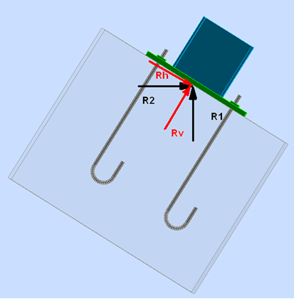
Fig. 3 Transformation of support reactions (R1, R2) to the local system of the base plate (Rh, Rv).
Loads - A Column Base Supported on Other Elements of the Structure
If there is no support defined at a node, Robot analyzes all elements adjoining the node and positioned above the base plate, on the side of the column pier. Next, it calculates the resultant set of all internal forces from these elements, also considering concentrated forces and moments applied to the analyzed node. Thus calculated resultant force is transformed to the local system of the base plate.

Fig. 4 All internal forces (Fvi, Fhi, Mi) and concentrated forces (such as Fv) are added up and the corresponding resultants of these forces are transformed to the local system of the base plate (Rh, Rv, M).
It is assumed that the column base is loaded by all elements above the base plate (1, 2 and 3 in Fig. 5), while elements positioned in the plane of the base plate or below are ignored.
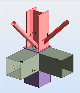
Fig. 5 The column base is loaded by elements: 1, 2 and 3, and is supported by elements: 7, 8 and 9.
Automatic Generation
Robot generates a column base automatically in the following 2 cases:
- If you selected only one supported element and the node where the column base should be defined (irrespective of whether a support at this node is defined or not) - see Fig. 6
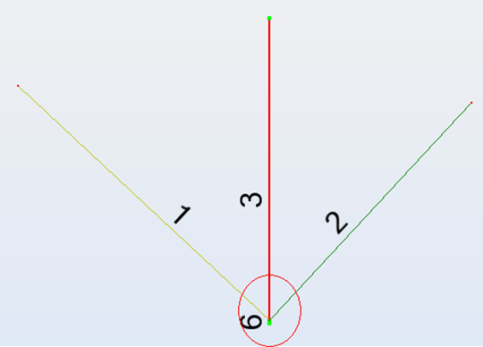
Fig. 6 The bar and the node are selected - Robot will generate a column base.
Note: The exception is when a selected node is an unsupported end of the cantilever (other bar elements do not adjoin to this node). Then the column base will not be generated (see Fig. 7).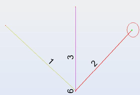
Fig. 7 An unsupported end - the column base will not be generated.
- If several members adjoin to a node and only one of them is from steel, while the remaining ones are from other materials, as in Fig. 8. , the column base is generated automatically for the steel member.
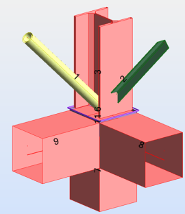
Fig. 8 Member 3 is the only steel element; members 7, 8 and 9 are RC elements; the column base will be generated for member 3.