The theoretical (required) reinforcement obtained after calculations is interpreted as follows.
-
Longitudinal reinforcement
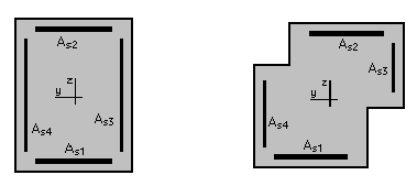
For biaxially bent columns with the rectangular, T-shaped, L-shaped or Z-shaped sections, areas of reinforcement should be interpreted as follows.
As1= As2 = Reinforcement along b.
As3= As4 = Reinforcement along h.

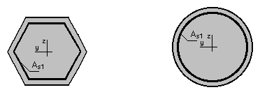
For columns whose cross section is described by a regular polygon, circle, semicircle or circle quarter, the areas of reinforcement should be interpreted as follows.
As1 = Reinforcement along b - evenly distributed along the edge.

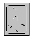
For rectangular beams bent biaxially:
As1= Bottom reinforcement. As2 = Top reinforcement.
As4= Bottom reinforcement (Z axis). As3 = Top reinforcement (Z axis).

For elements with reinforcement on both planes, the results should be interpreted as follows.

The areas are treated independently - they have no common parts in the corners. The corner area of section reinforcement is assigned to the area resulting from shearing in the Y plane.
-
Transversal reinforcement:
- Theoretical (required) stirrup spacing (Stirrup spacing) - spacing of the defined stirrups required for a given section.
- Real (provided) stirrup distribution - the distribution which is assumed for a given section once the element has been divided into N equal parts (defined earlier in the Calculation parameters dialog) and once the distribution in each of the zones has been calculated.
- Transversal reinforcement type / distribution - presents the stirrup type and distribution in the number of zones defined earlier in the Calculation parameters dialog. The reinforcement type is described by the number of bars and their diameter linked by the letter f or a steel grade (according to code). The designation 5f8 (4HA8, 4T8) denotes four-legged stirrups made from the bars of φ8. The description of the distribution for each zone includes the number of stirrups and their spacing linked with a multiplication sign. The zones are linked with an addition sign.
The following description: 20*4.0+10*8.0+20*4.0 denotes three zones of stirrup distribution. The first one and the last one comprise 20 stirrups each spaced every 4.0 units of section dimension. The middle zone comprises 10 stirrups spaced every 8.0 units of section dimension. The valid units are the units according to which calculations were performed.

The design combination shows the most unfavorable set of forces for a given section. It is only one of the components of the envelope of sets of forces. Yet each of these sets may affect the final required reinforcement area. This is the reason why the design combination as a single component may not be used to design the whole section.