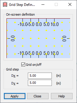
Open the Grid Step Definition dialog, which modifies the grid step displayed on the screen, using either method:
- Click View menu > Grid > Grid Step Definition
- Click
 .
.

Note: You can also access this dialog and edit the grid step after selecting one of the main commands (definition of elements, for example).
Note: The shape of the dialog depends on the type of coordinates used and the type of structure (plane or 3D).
The dialog has the following parts:
- Upper, where you can define the grid step graphically.
- Lower, where you can enter values in fields for the grid (DELTA 1-3). The fields differ based on a grid type.
You can define the grid step 2 ways:
- Graphically, using the grid drawn at the top of the window, you define a rectangle of required dimensions. After the rectangle is created, the field in the dialog is redrawn according to the selected grid step, and the corresponding values are entered in the fields. When the cursor is positioned at the top of the window, it appears as a cross; the background color in this portion of the dialog is identical with the background color in the 3D module; the grid is drawn in the following way:
- The current grid points are brightly displayed (Note: One of the points should be positioned in the center of the defined area).
- Points used to define the new grid are darker:
- Around the central point, the spacing is equal to 0.1 of the current one.
- Between the first and second grid rectangle, the spacing is equal to 0.2 of the current one.
- Between the second and third grid rectangle, the spacing is equal to 0.5 of the current one.
- New grid points are not drawn between other rectangles.
- The spacing between the points of the existing grid at the top of the window is scaled to fit at least 6 points vertically.
- The organization of the polar coordinate system is similar.
- Entering values for the grid step in fields (current units are used); after the dialog is opened, the current step values are displayed in the fields; the step at the top of the window is updated when the field is closed. If nothing was entered in the field or the previous value was deleted, the previous value is accepted as the step. The number of displayed fields depends on whether the structure is a plane or 3D:
- For plane structures, 2 edit fields are displayed:
- For Cartesian system: Dx and Dy with the current length unit.
- For polar system: Dr and Da with the current length and angle unit.
- For 3D structures: Dz with the current length added.
- For plane structures, 2 edit fields are displayed:
The new grid step is entered into the 3D window by clicking Apply.