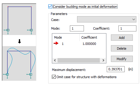
Use this dialog to generate a structure model which includes deformations induced by a selected buckling mode or linear combination of modes.
- Access
-
- Click
 (Analysis Parameters) in the standard toolbar, and then go to the Buckling Deformation tab.
 - Click Analysis
 Analysis Types, and then go to the Buckling Deformation tab.
- Click
Deformations do not cause initial forces or stresses in a structure. If deformations are considered, it results only in changing the structure geometry.

To apply buckling deformation, define the buckling analysis case and perform structure calculations. The change of structure geometry results in the deletion of a deformed structure. It is thus necessary to carry out structure calculations again for the initial structure (new buckling modes) and for a deformed structure. All results are displayed on the deformed structure, whereas nodal displacements are specified in relation to the initial user defined geometry.
Consider buckling mode as initial deformation toggles consideration of deformation for a structure. When off (default), all options in the dialog are inaccessible. If on, options in the dialog are accessible and structure deformation parameters can be defined. Click Apply to accept the change (switching on or off deformations). Click Close to diregard changes.
The Parameters field includes the Case selection list containing buckling cases defined for a structure. Buckling deformations are based on a selected buckling case. The Mode and Coefficient fields determine the number of a buckling mode and the coefficient with which the selected mode will be included in a linear combination. The mode and coefficient may also be selected from the list of modes and coefficients. Click on a selected line on the list enters the mode number and the coefficient to the Mode and Coefficient fields. Adding, deleting and modifying elements are possible by clicking the appropriate button. Note that adding an element results in the overwriting of old values.
Deformations can be scaled after defining a value in the Maximum displacement field. The value enables scaling a selected mode or mode combination.
If the Omit case for structure with deformations option is deselected, a given buckling case will be calculated for a deformed structure. If selected, the case will be omitted during calculations.
After changing the structure geometry, the result status changes to Not Available, therefore, structure calculations should be performed again.
Thus, calculations for a structure with buckling deformations defined are conducted in two stages:
- Stage 1 - Calculations of an initial structure (without deformations)
- Stage 2 - Calculations of a deformed structure.
Both stages are carried out automatically.