Use this dialog to set up a wind load simulation and generate wind loads.
Access
- Click
Loads
 Wind loads simulation
 Generate Wind Loads.
General tab
- Wind direction
- Shows the list of wind directions according to the global coordinate system. By default, the X+ direction is selected.
- Wind parameters
- Specify the wind velocity, pressure, and ground level.
- Wind exposure
- Specify which elements are exposed to the wind, and indicate if the openings in the panels must be considered as closed or not.
- Loads generation
- Select
Averaging pressure on the elements to apply the wind pressure as an average load on panels. Otherwise, the load will be more detailed and applied over the finite mesh of the panel.
Note: Loads generated onto columns, beams, and claddings (panels without stiffness used for load distribution to members) will remain uniform with averaged values.
- Specify how you want to generate the wind loads:
- Automatically with a convergence threshold for the deviation factor
- Manually
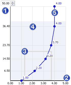
Wind Profile tab
Use the Wind Profile tab to create a variable wind profile.
- Wind profile: Graphic elements
-
To create a wind profile, click anywhere on the graphic curve to create a point, and then drag this point to the required coefficient.
-
Height
Allows you to adjust the wind profile curve, or to expand it beyond the virtual wind tunnel range.
This option is useful if you want to save a wind profile in order to apply it to other buildings.
-
Velocity factor
The multiplying factor which refers to the velocity of the base wind.
-
Building outline
Shows a summary representation of the building size.
-
Wind tunnel (light blue area)
Graphic representation of the virtual wind tunnel.Note: The size of the virtual wind tunnel is set automatically, based on the size of the building. If the wind profile is bigger than the size of the wind tunnel, the simulation takes into account the wind loads in the inner limits of the wind tunnel only.
-
Wind curve
Curve representing a wind profile in a virtual wind tunnel.
-
Height
- Name
- Enter a Name for the wind profile that you want to save.
- Once saved, the profile name is added to the drop down list which allows you to select a saved profile.
- <Load Wind Profile>
- Contains the list of wind profiles if you created any.
- Reset
- Restores the default wind profile.
Loads generation process
When the analysis is started, the following elements display.
- Display
- Click Pressure on elements to display the pressure scale on the faces of the model.
- Click Pressure scale to change the color palette of the scale.
- Resultant forces
- Displays the resultant forces acting on the structure in the three main directions, and their changes in the simulation time.
- Wind compatible: in the wind direction.
- Perpendicular: perpendicular to the wind direction.
- Vertical in the vertical direction, according to the global 'Z' coordinate.
- Convergence process
- Displays the maximum resultant force value against the reference value of the deviation factor.
- Forces above the reference value are shown in red, and forces below the reference value are shown in green.
Note: If the automatic generation is enabled, loads are generated when all resultant forces are inferior to the reference value of the deviation factor.
- Generate loads now
- Stops the simulation and creates the calculated wind loads on elements.
Note: It is possible to stop the simulation in the manual mode as well as in the automatic mode. If you selected several wind directions, then clicking this option generates a load case for the current wind direction, and a new simulation starts for the next wind direction.