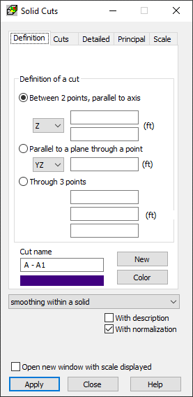
Select the Definition tab in the Solid Cuts dialog to adjust presentation quality.

In Drawing maps on cuts through solids, all section maps are drawn for the same result quantity. It is a main difference compared to diagram presentation on panel cuts where each diagram has a different result quantity selected.
For results dependent on the local direction in a finite element, the direction is determined independently from the cut plane. For example, if stress map Sxx is displayed, then the stress direction x will be user defined independently from the cut plane.
Maps on cuts are only a different form of drawing maps for a quantity selected in the Maps on Solids dialog. It is possible to display a map on a solid external contour or on internal cuts through a solid.
This tab defines solid cuts made by means of a plane. Operation and contents of the tab for cut definition is analogical as cut definition for shell structures.
The following cut definitions are allowed.
- By means of a vertical plane defined by two points. This generates a vertical strip limited by two points in the plane parallel to the global Z axis.
- As a cut parallel to the selected principal plane (XZ, XY, ZY) in the global coordinate system, passing through a defined point.
- By means of a plane defined by three points in space.
To define a cut for a structure, do the following.
- Select the cut definition method.
- Determine cut parameters.
- Assign a name to the defined cut.
- Select the cut color.
- Click New.
The defined cut will be added to the list of available cuts on the Cuts tab.