After selecting the Parameters tab in the Definition of non-linear hinge model dialog, the following dialog displays.
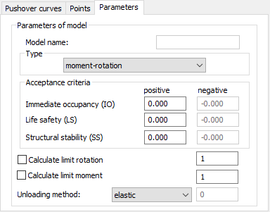
The top of the dialog has a diagram of the hinge model.
Model name displays the name of the selected hinge model. This tab has options for determining a hinge model type and defining model parameters
The units are displayed on a diagram: abscissa: Displacement (mm), Rotation (rad) or Strain, ordinate: Force (kN), Moment (kN*m), or Stress (MPa).
After you select the Stress-strain type from the list in the Type field, the options: Calculate limit rotation and Calculate limit moment are not available.
For Acceptance criteria, the following options are available:
- Immediate Occupancy - The post-earthquake state in which a structure suffered minimal or negligible damage. Non-structural elements (partition walls and so on) remain unimpaired. The building does not pose a risk of life-threatening injury and can be safely occupied.
- Life Safety - The post-earthquake state in which a structure suffered considerable damage, although main load-bearing elements remain unimpaired. There is a low risk of life-threatening injury inside and outside the building. Reoccupation requires substantial repairs, although they might not be economically viable.
- Structural Stability - The post-earthquake state in which a structure is on the verge of total destruction. There is a high risk of life-threatening injury from pieces falling from the building. The building requires major repair; however in most cases, the repair is not economically viable.
When Symmetry is selected on the Points tab, the negative fields in the Acceptance criteria field are not available. The values are copied (and the sign is changed to the opposite) from the positive fields
When Calculate limit force (displacement) is cleared, the values defined in the table on the Points tab are absolute quantities expressed in the appropriate units. These units are recalculated when the units change.
When Calculate limit force (displacement) is selected, the values defined in the table on the Points tab are unit-less quantities which are determined based on the code-defined function diagrams compared to the reference quantities, that is, to limit force and/or limit displacement evaluated during calculations for each bar separately. These values on diagrams are not recalculated when units change.
The reference values for forces and displacements depend on the data for the section material, and on the remaining characteristics of the bar (bar length, for example) on which a hinge is defined. The reference values for Qce forces are defined as values for the positive semi-axis. The reference values of displacements are the (generalized) displacements corresponding to the reference value for Qce forces assuming the initial stiffness.
Robot automatically defines reference values of forces and displacements only for steel sections when the properties are saved in the database or you define them for:
- Bending (MY,MZ)
- Shear (FY,FZ)
- Longitudinal forces (NX).
If a different section (material) type has been selected or the section database lacks the data needed to determine the reference values, analysis is interrupted and the bar lacking data is highlighted. The analysis is possible when you define a characteristic for a given bar as an absolute value.
The reference parameters are from the comments available in the publication FEMA: NEHRP Guidelines for the Seismic Rehabilitation of Buildings, Chapter 5.
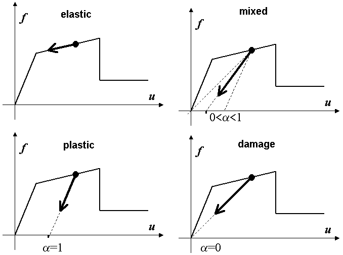
At the bottom of the dialog, the Unloading method field has the following unloading types (see the following image):
- Elastic - Return is along the same path as while loading.
- Plastic - Return is along the path defined by the initial modulus of elasticity a = 1.
- Damage - Return is along the path defined by the initial modulus of elasticity a = 0.
- Mixed - Return along the intermediate path between the plastic path and damage path determined by the parameter a : 0< a < 1.