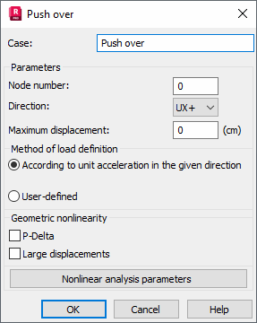
Use this dialog to set up Pushover Analysis parameters for a dynamic case.
- Access
-
- Ensure that a modal analysis has already been defined.
- Click Analysis
 Analysis Types
  New.
New. - Select Push over in the Analysis Type dialog, and then click OK.

- Case
- The name of the load case.
- Parameters
-
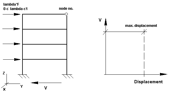
- Node number - The number of a structure node belonging to the structure roof (see the figure below).

- Direction - Direction of an external factor affecting the structure in the global coordinate system.
- Maximum displacement - Maximum displacement in the selected structure node.
- Node number - The number of a structure node belonging to the structure roof (see the figure below).
- Method of load definition
-
- According to unit acceleration in the given direction - Determines a displacement vector during the pushover analysis.
- User-defined.
Note: The According to unit acceleration in the given direction option uses the following algorithm.- Calculation of the vector
 , where K, M - stiffness matrix and mass matrix, respectively, Idir - unit direction vector; Φ dir - push mode vector.
 - Normalization:
 , where
  .
. - Definition of mass participation factor: Γ dir = (M Idir , F dir).
- Definition of lateral forces as: Fdir = γdir M Φ dir , where γdir is a scalar multiplier.
The right-hand side of the equation system presented in point 1 can be defined with a static load case that will make up a set of forces applied to the structure. The algorithm of calculation of lateral forces (points 2, 3, 4) is identical to that described above.
- Geometric nonlinearity
-
- P-Delta - Select this option to consider P-Delta effects during the analysis.
- Large displacements - Select this option to take into account large displacements and/or rotations during the analysis.
- Nonlinear analysis parameters - Opens a dialog which allows you to set up the options of the nonlinear analysis.
See also: