In addition to viewing measurement information in the CAD view, you can see all an item's measurements using the Info tab at the bottom of the Graphics window. The tab contains the following areas:
|
Area |
Information displayed |
|---|---|
|
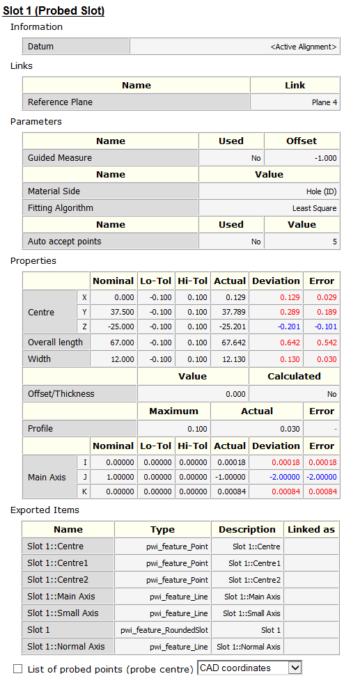
Information |
The datum or alignment relative to which the item measurements are reported. |
|
Links |
Any sequence items used by the selected item. In the following example, the slot is measured by projecting it onto Plane 4. |
|
Parameters |
The parameters controlling the measurement of the item. |
|
Properties |
The position and size of the feature, the tolerance values, and the deviation and error values (as seen in the report). The area also displays the form value of the item when appropriate. |
|
Exported Items |
The properties that can be used by other items in the inspection sequence. |
|
List of probed points |
The positions, vectors, and deviation from form for each probed point. The Used column indicates whether the point is included in the item's measurement calculations. |
To use the Info tab:
- At the bottom of the PowerInspect window, click the Info tab.

- In the inspection sequence, select the item for which you want to display the details.
As with labels, when the measurements are compared to the item's nominals, different colours are used to indicate whether the measurements are above (red text), below (blue text) or within tolerance (green text). For example:
- To display the details of the probed points used to measure the feature, select the List of probed points check box. For example:
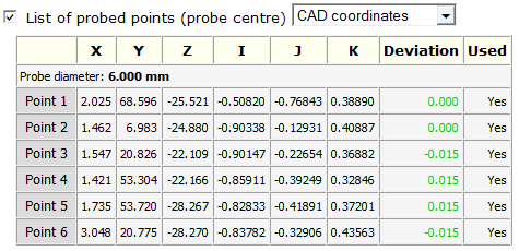
To specify the location relative to which the values are measured, select an entry in the drop-down list.