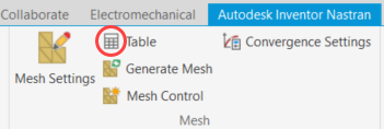
Rather than use the Global mesh settings, we will use the Mesh Table to assign element sizes on a per-part basis.
- Click
Autodesk Nastran
 Mesh Table.

The Mesh Table dialog box appears. Refer to Figure 1.a – 1.f for the next six steps.

Figure 1.a – 1.f
- Select the checkbox in the header row of the last column. All checkboxes in this column become checked. Changes made in the table for one part will be copied to all parts.
- Type 3.7 into one of the cells in the Size column and press Enter. The size of 3.7 mm is applied to all parts.
- Deselect the checkbox in the header row of the last column. All checkboxes in this column become unchecked. Changes made in the table will only affect one part.
- Type 1.5 into the bottom row of the Size column. We want a finer mesh size for the Welds parts.
- Deselect the Continuous Mesh checkbox. It is not necessary for the nodes to be matched where adjacent parts meet. Additionally, a discontinuous mesh also better facilitates the differing mesh sizes of the parts.
- Click OK to accept the settings and close the Mesh Table dialog box.
- In the ribbon, click
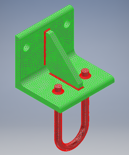
 Generate Mesh. The model appears as shown in the following image:

| Previous Topic: Define the Materials and Element Properties | Next Topic: Create Contact Between the Parts |