This tutorial demonstrates how to gradient around a building footprint that has relatively complicated geometry and variations in level.
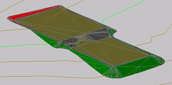
The drawing used in this tutorial contains a surface and a building pad that consists of two tiers connected by a small ramp. The level of the top portion of the building pad is 402 feet, and the bottom portion is 400 feet.
Projection grading, also known as slope grading, involves projecting a gradient from a feature line to a specified target. Projection grading targets include a junction with a surface, or a specified distance, level, or level difference. The ramp that connects the two tiers consists of arcs and inside corners, both of which complicate a grading plan. Simply applying projection grading, which was demonstrated in the Creating a Grading exercise, would result in a grading that overlaps itself.
In this tutorial, you will learn how to create a successful grading solution for similarly complicated scenarios. After you have completed this tutorial, proceed to the Using Feature Lines to Modify a Grading tutorial to learn how to modify the grading solution, using the Autodesk Civil 3D feature line editing tools.