In this exercise, you will use the reference text component to create a single label style that annotates two objects of different types.
The Reference Text label component is used to annotate multiple types of objects with a single label. You can insert references to surfaces, profiles, plots, and alignments. Each reference text component can refer to only one Autodesk Civil 3D object. If you need a label style to refer to several objects, create a separate reference text component for each referenced object.
In this exercise, you will create a label style that displays the alignment chainage and surface level at each horizontal geometry point.
This exercise continues from Exercise 5: Changing a Label Style.
Create a label style that refers to another object
- In Toolspace, on the Settings tab, expand the Alignment
 Label StylesChainageGeometry Point collection. Right-click Perpendicular With Tick And Line. Click Copy.
 - In the Label Style Composer dialog box, on the Information tab, for Name, enter Surface Level at Alignment Chainage.
- Click the Layout tab.
You can use this tab to create and edit label style components. You will modify the existing line and geometry point components, and then create two new label components for the new label style. The first component will display the surface level, and the second component will display the alignment chainage.
- Under Component Name, select Line. Specify the following parameters:
- Start Point Anchor Component: Tick
- Start Point Anchor Point: Middle Center
- Length: 15.00mm
- Under Component Name, select Geometry Point & Chainage. Specify the following parameters:
- Anchor Component: Line
- Anchor Point: End
- Attachment: Middle Left
- X Offset: 2.00mm
- Click the arrow next to
 . Click
  Reference Text.
 A reference text label component refers to other object types in the drawing, instead of to the object type you are labeling. In this case, the reference text component will refer to a surface object.
- In the Select Type dialog box, select Surface. Click OK.
- In the Label Style Composer dialog box, specify the following parameters:
- Name: Level
- Anchor Component: Geometry Point & Chainage
- Anchor Point: Bottom Left
- Attachment: Top Left
- Under Text, in the Contents row, click the Value cell. Click
 .
. - In the Text Component Editor dialog box, in the preview pane, replace Label Text with EL:. Under Properties, select
Surface Level
. Click
 to move the Surface Level property to the preview pane.
 The property block in the preview pane should look like this:
EL: <[Surface Level(Um|P3|RN|AP|Sn|OF)]>
- Click OK.
- In the Label Style Composer dialog box, click the General tab. Set the Flip Anchors With Text property to True.
Using this setting ensures that when the labels are flipped to maintain plan readability, they will display as mirror images of the original labels.
- In the Label Style Composer dialog box, click OK.
This exercise uses Labels-5c.dwg with the modifications you made in the previous exercise.
To apply the label style that refers to another object
- In the drawing, pan to the junction of the Main Street and East Street alignments.
- Click tab panel menu
 . Click one of the chainage labels on the East Street alignment.
 - In the Alignment Labels dialog box, specify the following parameters:
- Type: Geometry Points
- Geometry Point Label Style: Surface Level At Alignment Chainage
- Click Add.
- In the Geometry Points dialog box, click
 to clear all check boxes. Select the Alignment Beginning check box. Click OK.
 - In the Alignment Labels dialog box, click OK.
- Drag the label to a clear location, if necessary.
Notice that the label is added to the alignment, but the level value is displayed as ???. These characters are displayed because you have not associated a surface with the Level component.
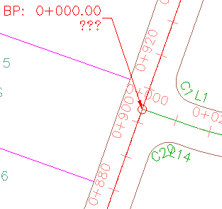
Label style that refers to an alignment and surface, with no surface associated with the label
- Ctrl+click the Surface Level At Alignment Chainage label. Right-click. Click Label Properties.
- In the Properties palette, under Reference Text Objects, click the cell to the right of
Surface Level At Alignment Chainage
. Click the drop-down list and select the surface name that appears in the list.
Examine the label. The surface level at the junction of the alignments is now displayed.
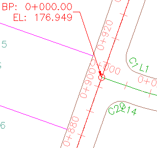
Label style that refers to an alignment and surface
- Press Esc to deselect the label.
To continue to the next tutorial, go to Using Expressions in Labels.