In this exercise, you will edit the parameters at several corridor sections.
You will edit a section in two ways. First, you will modify a subassembly parameter at a single chainage, which will override the subassembly settings for that chainage only. Second, you will modify a subassembly parameter, and then apply the modification to a range of stations.
This exercise continues from Exercise 1: Viewing Corridor Sections.
Modify subassembly properties for a single chainage
- On the Chainage Selection panel, in the Select A Chainage list, select 7+75.00.
- On the View Tools panel, click Zoom To Subassembly Find.
- In the Pick Subassembly dialog box, select Lane (Right). Click OK.
- On the Corridor Edit Tools panel, toolbar, click Parameter Editor
 .
.
- In the Corridor Parameters dialog box, in the Assembly - (1) tree, under Group - (1), expand Lane (Right).
Notice that identical values are displayed in the Design Value and Value columns. The Design Value column displays the value that was specified when the subassembly was added to the assembly. The Value column displays the actual value of the subassembly at the current chainage. In the following steps, you will override the Design Value at the current chainage, and then examine the results.
- Change the Width Value to 36.0000’.
Notice that the Override check box is automatically selected, which indicates that the Design Value has been overridden at this chainage.
- Click Go To Next Chainage Find several times.
Notice that for the other chainages, the WidthValue is 12.000’. The lane subassembly that is displayed in the section view updates in width to reflect the width at the current chainage.
- On the Chainage Selection panel, in the Select A Chainage list, select 7+75.00.
- In the Corridor Parameters dialog box, in the Assembly - (1) tree, under Group - (1), under Lane (Right), in the Width row, clear the Override check box.
The Value column displays the same value as the Design Value column.
This exercise uses Corridor-4a.dwg from the previous exercise.
Modify subassembly properties for a range of stations
- On the View Tools panel, click Zoom To Extents Find.
- On the Chainage Selection panel, in the Select A Chainage list, select 4+50.00.
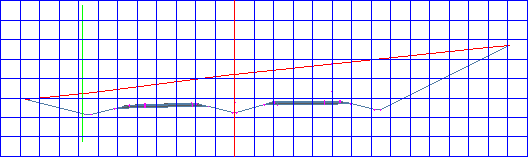
Notice that the road is in a shallow cut on one side and deep cut on the other. The criteria set for the daylight subassembly caused it to use a 6:1 gradient on the left side, and a 4:1 gradient on the right side. Also notice the superelevation transition of the road. At chainage 4+50.00, the lanes are relatively flat.
Note:For more information about superelevation, see the Applying Superelevation to an Alignment tutorial.
- On the Chainage Selection panel, in the Select A Chainage list, select 7+75.00.
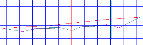
Notice the superelevation transition at this chainage. Using the Centerline Pivot option on the depressed central reserve subassembly causes the lanes and shoulders to superelevate about a point above the centerline ditch. A straight edge laid against the lane surfaces would pass through the profile gradient point.
- In the Corridor Parameters dialog box, in the Assembly - (1) tree, under Group - (1), expand Central Reserve.
Notice that the Centerline PivotDesign Value is set to Pivot About Centerline.
- In the Centerline Pivot? row, click the Value cell. Select Pivot About Inside Edge of Carriageway .
- On the Corridor Edit Tools panel, click Apply To A Chainage Range Find.
- In the Apply To A Range Of Stations dialog box, notice that Start Chainage is 7+75.00, which is the current chainage. For End Chainage, enter 11+00.00. Click OK.
- On the Corridor Edit Tools panel, click Update Corridor Find to update the corridor model.
- View the corridor section at chainage 7+75.00.
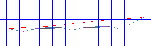
Notice that the profile gradient is held at the inside edges of carriageways and the lanes and shoulders pivot about this point.
- To view the gradient at subsequent chainages, click Go To Next Chainage Find.
Notice that the change you made is visible through chainage 11+00.00. At chainage 11+25.00, the Centerline Pivot?Value returns to Pivot About Centerline.
To continue to the next tutorial, go to Viewing and Rendering a Corridor.