In this exercise, you will use the feature line editing tools to modify plot plot line geometry.
You will use two different methods to change the geometry of the two large plots at the end of the cul-de-sac.
First, you will learn about the grips that are available on plot lines. You will use plot line grips with the feature line tools to change the geometry of a plot.
Second, you will join two separate plot lines, and then remove a intersection point from the combined plot line.
This exercise continues from Exercise 2: Swinging One End of a Plot Lot Line.
Add a intersection point to a plot plot line
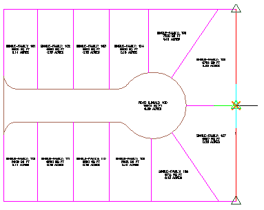
- Open Parcel-2C.dwg, which is located in the tutorials drawings folder.
- Select the back plot line that is shared by plots 105 and 106.
- Click Plot Segment tab
 Modify panel
  Edit Geometry.
The Edit Geometry panel is displayed in the ribbon.
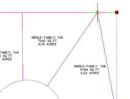
- Click Plot Segment tab Edit Geometry panel Insert PI.
- Snap to the intersection of the back plot line and the plot line that separates plots 105 and 106. Click to insert a intersection point.
- Press Enter to accept the default level of 0.
- Press Esc twice to end the command.
The back plot line now has an intersection point at the point at which the plots meet. With a PI in this location, you can edit the plot line on one of the plots without affecting the other.
Grip edit a plot plot line
- In the drawing, select the plot line that separates plot 104 and 105.
Notice the
 grip on the plot line. This grip is available on attached plot lines, which are created with the slide angle, slide direction, and swing line precise sizing tools available on the Plot Layout Tools toolbar. You can use this grip to slide the plot line along the plot line to which it is attached.
- Press Esc to deselect the plot line.
- Select the back plot line that is shared by plots 105 and 106.
Notice the
 grips on the ends of the plot line. These grips are available on plot lines that were created either from other Autodesk Civil 3D objects or the fixed line and curve tools available on the Plot Layout Tools toolbar. You can use these grips to change the endpoint location of a plot line.
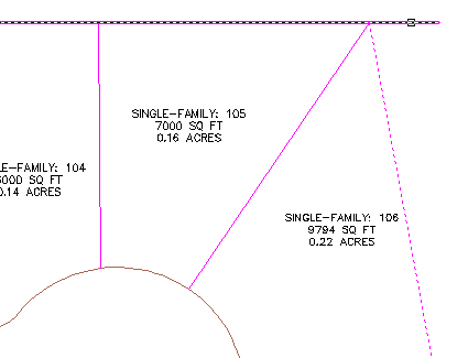
- Click the grip at the top of the plot line. Drag the grip toward the plot line that separates plots 104 and 105. Snap to the intersection of the three plot lines. Click to place the grip.
Notice that the area of plot 105 has changed. However, there is now an unnecessary plot line remaining to the North of the plot. You will delete the unnecessary portion of that plot line in the following steps.
Trim an extraneous plot plot line
- Click Plot Segment tab Edit Geometry panel
 Trim.
Trim.
- Select the back plot line of plot 105 as the cutting edge. Press Enter.
- Select the plot line that extends past plot 105 as the object to trim.
- Press Enter to end the command.
Break a plot plot line
- Click Plot Segment tab Edit Geometry panel
 Break.
- Select the back plot line that is shared by plots 106 through 110.
- On the command line, enter F to specify the first point to break.
- In the drawing, snap to the intersection of the back plot line and the plot line that separates plots 107 and 108. Click the intersection.
- Press Enter.
Two plot lines are created, separated at the point you specified.
Join two plot plot lines
- Click Plot Segment tab Edit Geometry panel
 Join.
Join.
- In the drawing, click the two plot lines that form the southeast corner of plot 106.
- Press Enter.
The two plot lines are now a single element.
Delete an intersection point
- Click Plot Segment tab Edit Geometry panel
 Delete PI.
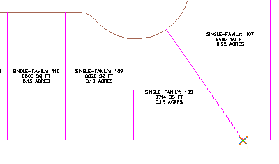
- In the drawing, select the plot line that forms the south and east boundaries of the plot.
- Click the green PI at the southeast corner of plot 108.
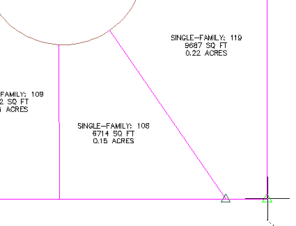
- Press Enter twice to end the command.
To continue to the next tutorial, go to Displaying and Analyzing Plots.