This lesson shows you how to create a pair of twisting horns. It uses extrusions and transforms; it also demonstrates spline extrusion as a simple alternative to multiple extrusions.
Once again, apply a Symmetry modifier to mirror the edits you make to one half of the helmet.
Set up the lesson:
- Continue working from the previous lesson or open helmet_03.max.
- If you opened the new file,
 select the helmet, and make sure the
 Modify panel is active.
Split the model in half and apply a Symmetry modifier:
- On the ribbon
 Polygon Modeling panel, activate
 (Polygon).
Select the polygons on the left half of the helmet (from your point of view), and then press
Delete.
(Polygon).
Select the polygons on the left half of the helmet (from your point of view), and then press
Delete.
- Apply a Symmetry Modifier, and adjust its settings as described in an earlier lesson:
- Axis = Y
- Flip = on
- On the ribbon Polygon Modeling panel, click
 (Previous Modifier) to go to the Editable Poly level.
On the Modify panel, you can toggle
 (Show End Result) to see the Symmetry effect. If Symmetry has been set up correctly, turn this toggle off for now.
Adjust vertices at the base of the horn:
- On the ribbon Polygon Modeling panel, activate
 (Vertex).
- On the ribbon Edit panel Constraints group, activate
 (Constrain To Edge).
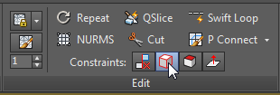
This ensures that the transform of any vertex will slide along the edges of the polygon to which it belongs.
- Activate the Front viewport. If you need to, click
 (Zoom Extents) to get a good view of the helmet.
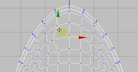
- On the main toolbar, activate
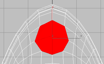
 (Select And Move), then select a vertex in the upper region of the helmet and move it as shown in the next illustration.
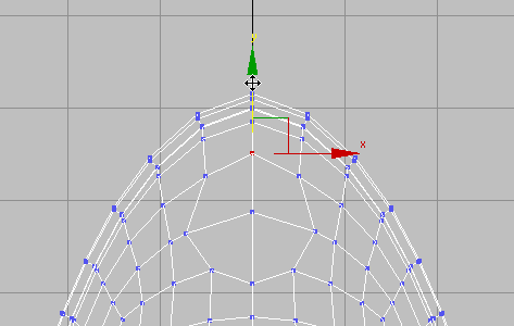
- Select the vertex that is opposite the central vertex, and
 move it as well. Also move the vertices above and below the central vertex. The goal is to create a symmetrical shape that is roughly circular.
- On the ribbon Edit panel, activate
 (Constrain To None).
Tip: When you forget that a constraint is on, surprising things can happen when you transform sub-objects. Because of this, it is a good idea to deactivate a constraint as soon as you have finished using it. Also, the buttons in this set behave like radio buttons. You can’t turn a constraint off by clicking its button a second time: You must activate Constrain To None to deactivate the currently active constraint.
(Constrain To None).
Tip: When you forget that a constraint is on, surprising things can happen when you transform sub-objects. Because of this, it is a good idea to deactivate a constraint as soon as you have finished using it. Also, the buttons in this set behave like radio buttons. You can’t turn a constraint off by clicking its button a second time: You must activate Constrain To None to deactivate the currently active constraint.
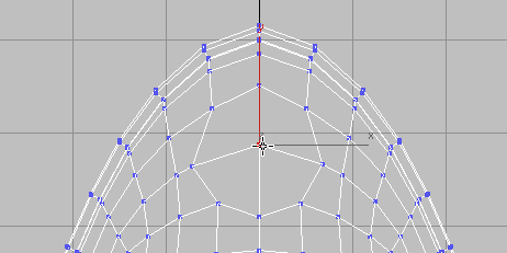
Create the base of the horn:
-
Select the vertex at the center of the circular group of polygons.
- On the ribbon Polygon Modeling panel,
Ctrl+click
(Polygon).
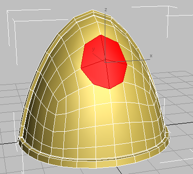
This automatically selects all the polygons that share the vertex.
- Switch the viewport back to a Perspective view, and
 Orbit so you can see all of the base of the horn.
- On the Polygons panel,
Shift+click
 (Inset).

- On the Inset caddy, drag the Amount spinner (the second control) to a value of approximately
0.25, and then click
 (OK).
(OK).
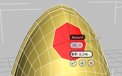
This creates an inset edge for the selected polygons.
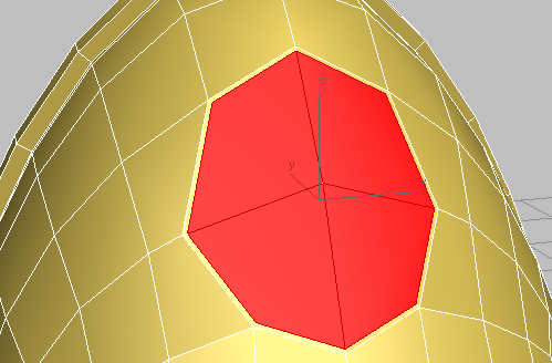
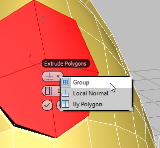
Use extrusion and bevel to create the socket for the horn:
- On the Polygons panel,
Shift+click
 (Extrude).
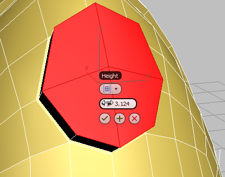
- On the first control of the caddy (extrusion type), choose Group from the drop-down menu.
- Set Extrusion Height to approximately
3.0, and then click
(OK).
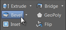
- On the Polygons panel,
Shift+click
 (Bevel).
- On the Bevel tool caddy, set the Height value (second control) to
0.25 and the Outline value (third control) to
–0.5. Click
(OK).
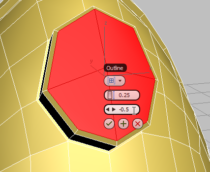
Helmet horn socket after first extrusion and bevel
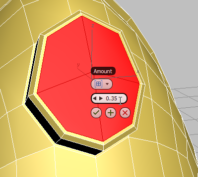
- On the Polygons panel,
Shift+click
(Inset).
- On the Inset tool caddy, set Amount (the second control) to
0.35, then click
(OK).
- On the Polygons panel, click
(Bevel).
- Drag the selected polygons slightly toward the inside of the helmet, then release the mouse and drag slightly down to bevel the extrusion slightly in toward its center. Click once to end the operation.
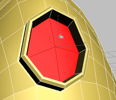
Horn socket after second inset and bevel
- Click
(Extrude) again, and drag away from the helmet until the polygons extend slightly beyond the socket. Click to end the extrude operation.
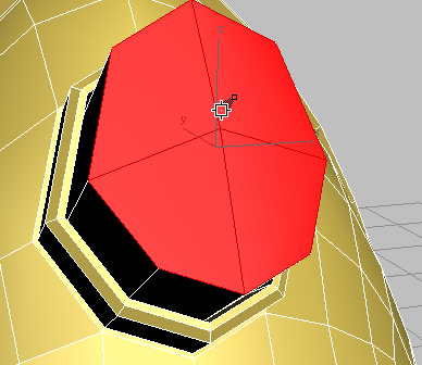
Helmet horn ready for spline-based extrusion
At this point, you could continue to create the horn by using the Move, Rotate, and Scale tools, coupled with the Extrude, Bevel, and Inset polygon tools. Instead, you will guide the extrusion by means of a path.
Draw a spline for extruding the horn:
- On the
 Create panel, activate
 (Shapes), then on the Object Type rollout, click to activate Line.
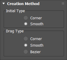
- On the Creation Method rollout, choose Smooth for both Initial Type and Drag Type.
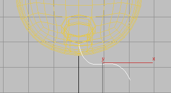
- Press
Alt+W to view all four viewports, and in the Top view draw a line extending from the horn socket. Click, drag, and click again, until you have created a line of four or five vertices. Right-click to end Line creation.
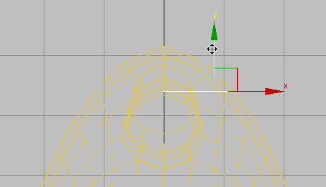
- In the Front view,
move the line along its Y axis until it is centered on the horn socket. Move it along the X axis too, if you need to.
- Go to the
Modify panel Selection rollout, and activate
 (Vertex).

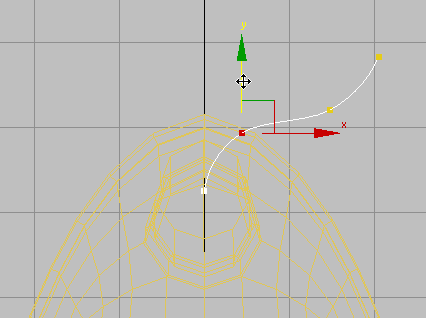
-
 Maximize the Perspective view and
move the line’s vertices until they form the shape of the horn you want to create.
Maximize the Perspective view and
move the line’s vertices until they form the shape of the horn you want to create.
-
Double-check and refine your Line edits in the other viewports.
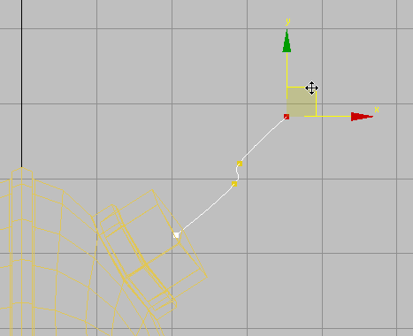
Left view
- Click
 (Vertex) once more to turn it off.
Extrude the horn:
-
Select the helmet, then on the ribbon Polygon Modeling panel, click
(Previous Modifier) to go to the Editable Poly level.
- Activate
(Polygon).
Important: If the four faces at the top of the base of the helmet are no longer selected, click and Ctrl+click to select them again.
- Click
 (Show End Result) to turn it on.
- On the Polygons panel drop-down panel,
Shift+click Extrude On Spline.
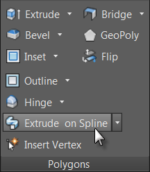
The caddy controls for spline extrusion are more numerous than for most caddies.

- Click the last of the controls, Pick Spline, and then click the spline you drew earlier.
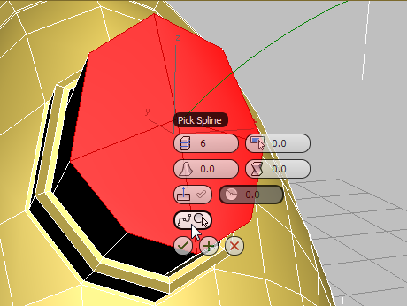
After you click the spline, 3ds Max grows horns, but these have no taper, yet.
- (Optional.) On the caddy, click Extrude Along Spline Align to turn it on.
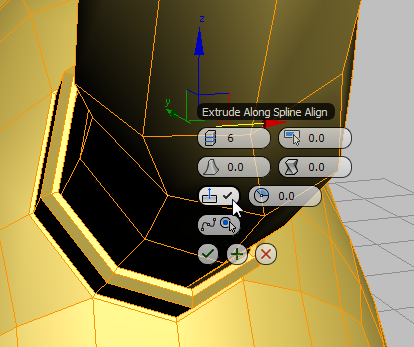
3ds Max aligns the spline to the normals of the original faces, making the horns more perpendicular to the rest of the helmet. This might or might not be a good effect, depending on the spline you drew.
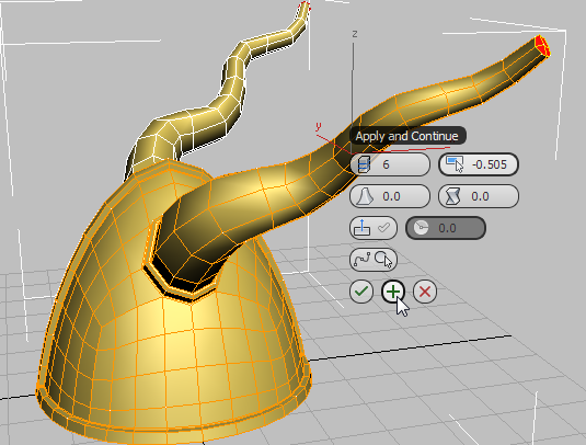
Note: You can also try adjusting the values of Twist and Rotation (available only when Align is turned on). - Change the value of Taper Amount to about
–0.5, then click
 (Apply And Continue).
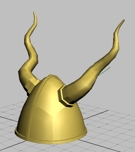
3ds Max extrudes the horns still further. This is easier to see in other viewports, but you can also navigate the Perspective view, as shown in this illustration.
- Change the Taper Amount so the horns come to a point (for the illustrated helmet, the value was
–0.955). Click
(OK) to finalize these changes and finish creating the horns.

By extruding the horns along a path, you saved yourself a great deal of back-and-forth between the transform and polygon modeling tools.
- On the ribbon Polygon Modeling panel, click
 (Polygon) again to deactivate it.
Unify the helmet geometry once again:
- Convert the object to editable poly format by opening the Polygon Modeling panel expansion (click the Polygon Modeling label) and choosing Convert To Poly. Then press
F4 to turn off edged faces.
The Symmetry modifier is removed and all the mirrored polygons are integrated into the model.
- Press F4 again to turn edged faces back on.
Save your work:
- Save your scene as my_helmet_04.