 Mesh Positioning
Aligns a scanned source mesh (from some area of an object) to a destination mesh (or surface) by specifying regions where the data matches on both.
This is useful for updating a digital model based on scan data, after the physical objects have been modified in some areas, and rescanned.
Access this tool from the Mesh tool palette:
Mesh Positioning Control options
Deviation statistics
Deviation Average/Standard Deviation/Deviation Maximum
Display fields showing deviation values between the source mesh and target objects after alignment.
Positioning Controls
Transform Mode
Translate and Rotate – The source mesh can be both translated and rotated during alignment.
Translate Only – The source mesh can be translated only.
Rotate Only – The source mesh can be rotated only.
Translate Direction
The source mesh is translated along the selected axes: X, Y, and/or Z.
Rotational Axis
The source mesh is rotated along the selected axis (X, Y, or Z), or along all three axes (Free).
Show Deviation Map
Turn on this option to show the color-coded deviation map.
Calculate map over selected region
The color-coded deviation map is only calculated over the selected region(s) on the mesh. The rest of the mesh is shaded in a uniform color.
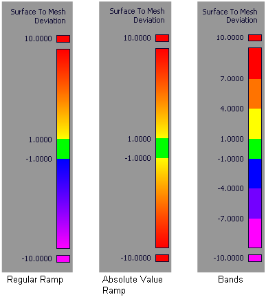
Ramp Distance
Maximum distance between source mesh and targets shown on the color ramp. Areas on the source mesh where the deviation is larger than this value are displayed in a solid color (red or purple).
Acceptable Distance
Upper limit for the acceptable deviation between source mesh and target(s). Regions of the source mesh where the deviation is smaller than this value are colored in green.
Where the value of the deviation is between the Acceptable Distance and the Ramp Distance, the surfaces display intermediate colors as shown on the ramp.
The Acceptable Distance also affects the stopping criteria when matching the source mesh to the destination.
Absolute Value Ramp
Turn on this option if you are not concerned with the direction of the deviation and simply want to view absolute deviation values.
Use Bands
Turn on this option if you want the ramp to display solid bands of color instead of slowly varying colors.
Advanced Controls
Sample density
Choose how many sample points are used from the selected regions of the source mesh.
Automatic – Uses an internal number of samples.
By percentage – Uses the Percentage of vertices value to calculate the number of samples.
Percentage of vertices
Percentage of the vertices from the selected regions of the source mesh that are used in the calculation.
A smaller value makes the calculations faster.
This option only appears if Sample density is set to By percentage.
Increase overlap by sliding mesh
Choose High, Medium, or Low to specify the degree to which overhangs (that is, regions of the source mesh that extend past the destination) are included in the calculations.
If you select Do not change, only the overlapping surface regions are sampled; overhangs are excluded.
In summary, High includes the most overhangs, while Do not change includes the least.
Consider local features(+/-)
Choose High, Medium, or Low to specify the degree to which local features (for example dips, or bumps) are taken into account in the calculations when positioning the source mesh.
A value of Low helps discard regions where the source mesh or destination presents some dips or bumps that do not have an equivalent on the other.
Mesh Positioning workflows
Align a mesh to other meshes or surfaces
Select the Mesh Positioning tool.
Select the mesh (scan) you want to position.
The mesh is highlighted in white.
Select one or more destination meshes or NURBS surfaces to align to.
The targets are highlighted in purple.
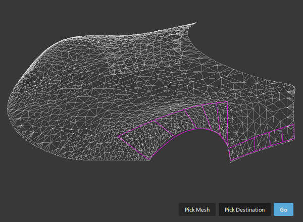 Note: If you need to de-select or select another source mesh or destination geometry at this point, click the Pick Mesh or Pick Destination button, and click the geometry to select or de-select.
Click the Go button at the bottom of the window.
A new series of buttons appears at the bottom of the window.
 Note: If Show Deviation Map was turned on in the control window, the source mesh is shaded with a deviation color map.
Use regions for positioning
Click the Match Region button.
Select the region(s) of the mesh that are matching the targets, by clicking down points to form polygonal selection area(s). Click the Select Region button before selecting each additional region.
All selected regions are highlighted in blue.
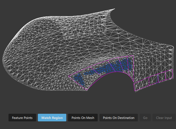
If you do not select any regions, the whole mesh is used.
Note: To de-select all regions, click the Clear Input button.To specify a rotation pivot or rotation axis, click the Add Pivot Constraints button, then click on the mesh in one or two locations respectively.
The points you clicked appear as locators lying on the source mesh. You can reposition them with the mouse.
Note: When specifying a rotation pivot or axis, the Transform Mode option is automatically set to Rotate Only to make the results of the re-positioning more predictable.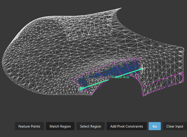
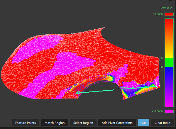
Click the Go button at the bottom of the window.
The source mesh (scan) is translated and rotated (according to the options specified in the control window) so that the selected regions achieve the best possible match with the targets.
A deviation color map is displayed on the source mesh (if Show Deviation Map is turned on.)
The Deviation Average, Standard Deviation and Deviation Maximum values are displayed in the control window.
Click the Go button repeatedly to iteratively converge on the best placement.
The alignment should improve and the deviation between source and target decrease with each iteration. Note that convergence of the iterations is only guaranteed when Transform Mode is set to Translate and Rotate.
Note: Use Edit > Undo to undo the last iteration.You can also change some of the options in the control window, then click the Go button to recalculate.
If you want to undo all the iterations and return the source mesh to its original position, click Undo All in the control window.
Use Feature Points for positioning
Instead of selecting matching regions on both the source and destination geometry, you can also specify matching points.
This method is most useful when the source or destination has features (for example grooves or bumps) not present on the other, or when the source is not already positioned in the vicinity of the destination.
Follow steps 1 to 4 from the previous workflow.
Click the Feature Points button at the bottom of the window.
New buttons appear.

Click down on the source mesh to position the first set of points.
The points appear as numbered bullets:
1,2,...NClick the Points On Destination button.
Click on the destination meshes or surfaces to position the points that should match the ones on the source mesh.
The points appear as numbered bullets:
1,2,...N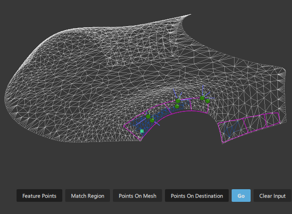 Note: At any time, you can add additional points to the source mesh or destination geometry by first clicking either the Points On Mesh or Points On Destination button.
Once all points are selected, click Go.
The source mesh is positioned so that the two sets of points achieve the best fit: point
Non the source attempting to match pointNon the destination.
About aligning a source mesh to a destination mesh
You can align a scanned source mesh (from some area of an object) to a destination mesh (or surface) by specifying regions where the data matches on both.
This is useful for updating a digital model based on scan data, after the physical objects have been modified in some areas, and re-scanned.
The input to this tool consists of a source mesh, (also referred to as the scan - for example, a re-scanned area of an object), and destination meshes or NURBS surfaces to which the source mesh must be aligned.
The source mesh is transformed so as to minimize the average deviation between the source mesh position and the destination meshes/surfaces.
During the iterative alignment of the scan data, you can restrict the rotation and translation along world space axes, as well as specify a rotation pivot or an axis of rotation.
To ensure fast and accurate results, an area of the source mesh should not have changed, and should match an area on the target object(s). However, the tool will still operate even if these areas are not exactly identical.