Parameterization UV
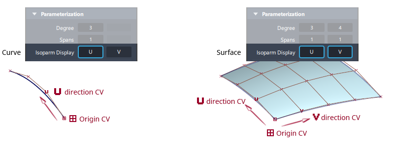
A parameter (U or V) is a mathematical value that describes the position along the length of a curve(U) or a surface(UV). This parameter is used by the software to calculate the XYZ position of every point of a curve or surface.
Different CV symbols  are used for the origin CV and the subsequent CV to indicate the U and V directions.
Modeling
Surface structure is always four-sided to respect the flow of U and V directions.
Holes and n-sided surfaces are achieved by trimming, which doesn't affect the UV parametrization of the surface.
Curves-on-Surface are defined in the UV parameter space of a surface not in the XYZ world space.
Visualization
The U and V surface directions define the orientation of a texture map.
The surface normal direction is set by the U and V directions. The normal can affect some visualization functions such as Ambient Occlusion calculations. See Normals and surface orientation in this section for more details.
Tools and workflow
When specifying a position on a curve or surface using snapping, for example using the Detach or Insert tools:
Ctrl- snaps to edit points or isoparmsAlt- snaps to halfway between edit points or isoparms
The following tools affect the display of UV parameters:
- Control Panel > Parameterization > Isoparm Display
- Draw Style - to change the display of V hulls.
- Color Themes > Customize - to change the colors of the U and V hulls.
- Arc Length
- Patch Precision
- Query Edit
The following tools can be used to modify the UV parameters:
The following tools have chord or uniform parameterization options:
Deep Dive: Chord and uniform parameterization
Most Alias tools default to uniform parameterization.
Uniform parameterization
Uniform parameterization assigns integer parameter values to the edit points and isoparms and evenly distributes the parameter value along the spans.
The first edit point is always parameter 0.0, the second edit point is always 1.0, the third is always 2.0, and so on.
Use the Arc Length locator with Ctrl snapping to examine parameter values:
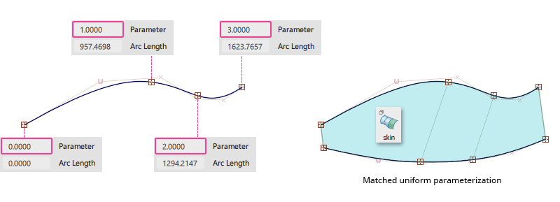
Surfaces built between uniform curves will connect edit points of the same parameter, creating the minimum number of isoparms.
Unlike chord parameterization, the parameters of a uniform curve have nothing to do with the actual length of the curve.
For single-span, Bezier geometry, chord and uniform geometry is the same shape when the CVs are in the same position.
Chord parameterization
Chord parameterization assigns parameter 0.0 to the start of the curve, then increases the parameter value proportionally to the chord length (shortest linear distance) between edit points.
The parameters of a chord-length curve are not integers. This means that building surfaces between chord-length curves can result in cross-knot insertion resulting in excessive isoparms.

Deep Dive: Degenerate Surfaces
Since surfaces are always four-sided to respect the flow of U and V directions, any boundary that has zero-length is called a degenerate edge. This typically causes problems with downstream modeling operations and gives poor highlights on the surface so is to be avoided.
Trimming is always recommended to create non four-sided surfaces instead of using degenerate edges.
Examples of degenerate edges
- An apparently three-sided surface with all the CVs on top of one another for the forth edge.
- Periodic primitives - Sphere, Cylinder and Cone. Alternative sphere types are available in the Sphere option window to avoid creating degenerate poles.
Identifying degenerate edges
- Pick a hull, and then use
Ctrland the arrow keys (Pick Walk) to step through sequential hulls and watch for the CVs to collapse onto a single point. - Use Pick > CV with a single click (not a drag select) and see how many CVs appear in the Pick Chooser list.
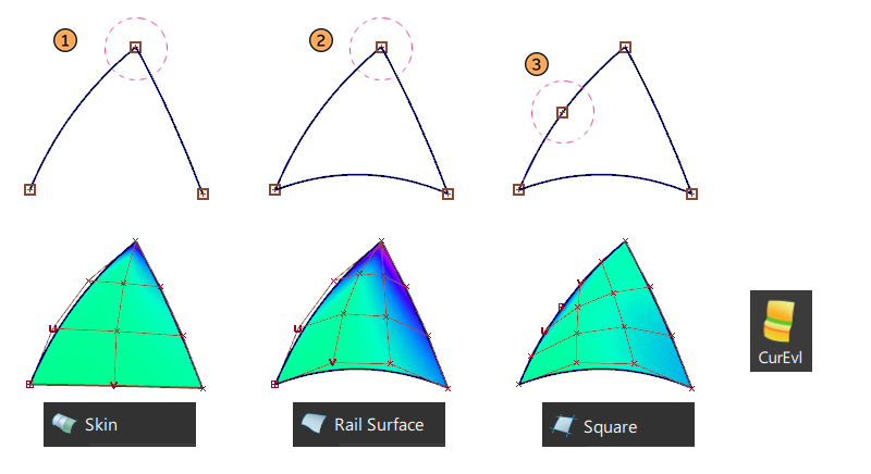
Modeling guidelines to avoid degenerate edges
Surfaces with degenerate edges have poor curvature and highlights so avoid zero-length edges:
- Skin: Avoid input curves touching.
- Bi-Rail: Avoid rail curves touching.
- Square and Rail: Avoid adjacent input curves being tangent.
Deep Dive: Mutli-knots
A multi-knot is where there are multiple edit points/isoparms at the same location in space, creating an empty span that eliminates one level of automatic continuity. For example, a degree 3 curve normally has curvature continuity (G2) at edit points.
- If you create a multi-knot of two edit points, you lose automatic curvature continuity so you only have tangent continuity (G1) at the multi-knot.
- If you create a multi-knot of three edit points, you lose both automatic curvature and automatic tangent continuity so you only have positional continuity (G0) at the multi-knot.
Multi-knots are generally undesirable as many CAD packages do not accept models with multi-knots and some Alias tools cannot work with them.
Multi-knots are generally caused by:
- Building geometry from complex trimmed edges. Using the Rebuild options in Rail and Square tools will re-parameterize inputs with multi-knots.
- Using rational geometry for circles.
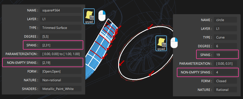
Displaying multi-knots
Multi-knots are displayed graphically when Query Edit is used with the RMB.
A multi-knot is an empty span, and so the difference between the spans and the non-empty spans gives the number of multi-knots.
Check Model in the Evaluate palette can also be used to locate multi-knots.