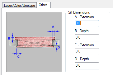
Use this procedure to change the sill dimensions for an opening in the Sill Plan display representation.
- Double-click the opening.
- Click the Display tab.
- Under the General category, for Display component, verify that *NONE* is selected.
- For Display controlled by, select This object. Note: To apply your changes to all openings in the drawing, select Drawing default setting.
- For Display representation, select Sill Plan.
- If necessary, expand Object Display Properties
 Advanced, and click
  Sill dimensions.
 - On the Sill Dimensions worksheet, enter the sill extension and depth dimensions.
Sill components A and B are for the outside of the opening. Sill components C and D are for the interior side.
- Click OK.
- In the Display component drop-down list, click the light bulb icons next to individual sill components to turn their visibility on or off as desired.
You can also access and modify sill dimensions and visibility settings through the opening’s context menu, as follows:
- Select the opening you want to change, right-click, and click Edit Object Display.
- In the Object Display dialog, click the Display Properties tab.
The current display representation is displayed in bold.
- Select the display representation where you want the changes to appear, and select Object Override. If Object Override is already selected, click
 at the upper-right corner of the tab.
 - Click the Other tab.

Opening sill dimensions
- Under Sill Dimensions, enter the sill extension and depth dimensions.
- On the Layer/Color/Linetype tab, under Visible, click the light bulb icons to turn on visibility for individual sill display components as necessary.
- Click OK twice.