Creates a 3D solid cylinder.
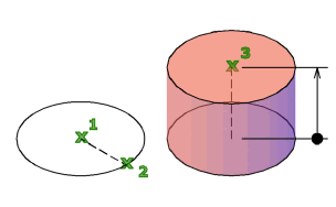
In the illustration, the cylinder was created using a center point (1), a point on the radius (2), and a point for the height (3). The base of the cylinder is always on a plane parallel with the workplane. You can control the smoothness of curved 3D solids, such as a cylinder, in a shaded or hidden visual style with the FACETRES system variable.

During a drawing session, the default value for the base radius is always the previously entered base radius value.
The following prompts are displayed.
3P (Three Points)
Defines the base circumference and base plane of the cylinder by specifying three points.
- 2Point
-
Specifies that the height of the cylinder is the distance between the two specified points.
- Axis Endpoint
-
Specifies the endpoint location for the cylinder axis. This endpoint is the center point of the top face of the cylinder. The axis endpoint can be located anywhere in 3D space. The axis endpoint defines the length and orientation of the cylinder.
2P (Two Points)
Defines the base diameter of the cylinder by specifying two points.
Additional prompts include
- 2Point
- Axis endpoint
TTR (Tangent, Tangent, Radius)
Defines the base of the cylinder with a specified radius tangent to two objects.
Sometimes more than one base matches the specified criteria. The program draws the base of the specified radius whose tangent points are closest to the selected points.
Additional prompts include
- 2Point
- Axis endpoint
Elliptical
Specifies an elliptical base for the cylinder.

- Center
-
Creates the base of the cylinder by using a specified center point.
Additional prompts include
- 2Point
- Axis endpoint
Diameter
Specifies the diameter for the base of the cylinder.

Additional prompts include
- 2Point
- Axis endpoint