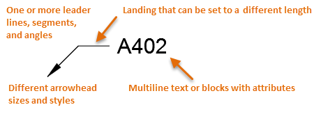
Some of the most common annotations in a drawing are labels and callouts. These convey various types of information and identifications depending on their content and symbols. The most advanced tool available for creating these objects in AutoCAD is the multileader tool, MLEADER. Here are some examples of multileaders that you can easily create.

The primary benefits of using multileaders over other methods include the following:
- A single, easily adjustable object with convenient grips
- Access to different types of labels and callouts with multileader styles
- Efficient edit and alignment options
Numerous options are available when you create one or more multileader styles.
Create a Standard Multileader
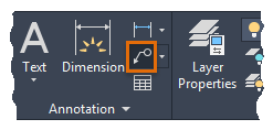
- On the Home tab, Annotation panel, click Multileader.
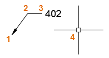
- Specify the start point of the arrowhead (1), the beginning point of the landing (2), and type 402 (3). Then, click somewhere else in the drawing area (4) to exit the command.
Just as is the case with dimension and text styles, multileader styles control what you place and what it looks like. Creating several multileader styles that suit your needs is the best place to start.
Create a Bubble Callout Style
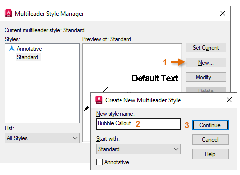
- On the Home tab, click the Annotation drop-down panel and then click the third control in the list.

- In the Multileader Style Manager, click New (1), type Bubble Callout as the new style name (2), and click Continue (3).
- Next, click the Content tab (1), change the multileader type from Mtext to Block (2). For the Source Block, choose Circle (3). Then click OK.
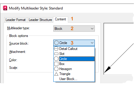
- In the Multileader Style Manager, click Close.
The new multileader style is automatically set to Current.
Create Multileaders
- Use the RECTANG command to create a small rectangle.
- On the ribbon, click the Annotate tab and locate the Leaders panel. The panel confirms that Bubble Callout is the current multileader style.
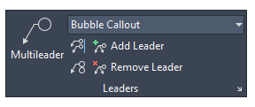 Tip: If you create many multileaders, you might prefer to use the Leaders ribbon panel for faster operation.
 - Click the Multileader tool on the left side of the Leaders panel.
- Using the Endpoint object snap, click a corner of the rectangle to specify the arrowhead location (1). Then click a location for the leader landing (2), type a letter or numeral in the Edit Attributes dialog box (3), and click OK.
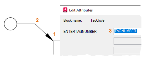
- Repeat the previous step to create something like the following illustration:
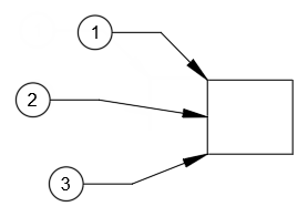
Modify Multileaders
- Select the rectangle and move it.
Notice that the arrowheads and leaders adjust when you moved the rectangle. By default, the multileaders are associative when the arrowheads are attached with object snaps.
- Click the Add Leader tool and select the top multileader (1). Specify another point on the rectangle (2).
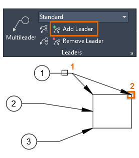
- Click the multileader Align tool and select the three multileaders.
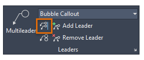
- Select the uppermost multileader as the alignment reference.
- Turn on Ortho mode with [F8] and click a point location vertically up or down to align them vertically.
The selected multileaders now align vertically as shown.
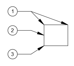
Adjust Multileaders with Grips
- Select the bottom multileader to display its grips.
- Hover over the middle, vertex grip to display a menu of options.

- Click the Stretch option and then click a new location a little higher up.
 Tip: Instead of clicking Stretch, you can click the grip itself to change the placement of the multileader.
 - Experiment with the other grips on either end of the multileader to familiarize yourself with them.
Note: Repositioning the grip at the end of the arrowhead ends its associativity. You'll need to use DIMREASSOC to reassociate the arrowhead with an object snap location of an object.
Experiment with Settings and Blocks
Try experimenting with different multileader style settings. For example, you can easily create a multileader style that looks like the following by changing settings in the Callout Bubble style.
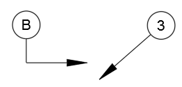
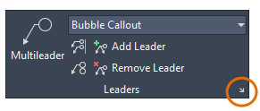
- Open the Multileader Style Manager.
You can also do this directly from the Annotate tab, Leaders panel, as shown.
- Select the style and click Modify.
- On the Leader Structure tab, clear the option, Automatically Include Landing.
- On the Content tab, click the Attachment drop-down and choose Insertion Point.
- Click OK and Close.
- Create several new multileader objects with the modified style.
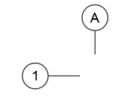
You can also create a multileader style for column grid labels that look like the following:
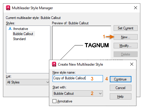
- Open the Multileader Style Manager again and click New (1).
- In the Create New Multileader Style dialog box, choose Start with: Bubble Callout, if necessary (2), type Column Labels and as the new style name (3), and click Continue (4).
- On the Leader Format tab, choose None for the arrowhead symbol.

- Click OK and then Close. With Ortho turned on [F8], create several column labels with the new multileader style.
Try experimenting with other settings and create your own block definitions with attributes. You'll find that the Multileader feature provides an efficient method to create and manage a variety of labels and callouts.
Create and Modify Multileader Objects
Here are the most commonly used commands and system variables related to creating and modifying multileader objects and their styles.
| Command | Description |
|---|---|
| MLEADER | Creates a line that connects annotation to a feature |
| MLEADERALIGN | Aligns and spaces selected multileader objects |
| MLEADERCOLLECT | Organizes selected multileaders that contain blocks into rows or columns, and displays the result with a single leader |
| MLEADEREDIT | Adds leader lines to, or removes leader lines from, a multileader object |
| MLEADERSTYLE | Creates and modifies multileader styles |
| System Variable | Description | Default Value | Saved In |
|---|---|---|---|
| GALLERYVIEW | Controls the type of preview in the ribbon drop-down galleries, including the drop-down list of multileader styles | 1 | Registry |
| MLEADERSCALE | Sets the overall scale factor applied to multileader objects | 1.0000 | Drawing |
Use the AutoCAD Help system to learn more about these commands and their related system variables. You can experiment with the system variable settings to find what works best for your needs.