To add fits or tolerances to dimensions, start the AMPOWERDIM command and add fits or tolerances.
If the default representation of the fit or tolerance is not satisfactory, select another representation from a predefined set available in the Representation drop-down list or the Method drop-down list in the Power Dimensioning Ribbon Contextual Tab.
If the predefined set is inadequate, you can use the System Editor and create your own customized fit representations and tolerance methods. The information on this page explains the related System Editor entries and keys.
The thumbnails of tolerances in the Tolerance drop-down correspond to the first eight entries under Acad/M > DimSet > Tols, in the System Editor. The names of these entries begin with “Tol” (for example, TolHigh). The remaining entries refer to the alternative unit representation of tolerances; their names end with “-Alt.” For example, TolHigh-Alt is the alternative unit representation of TolHigh.
System Editor entry mappings to tolerance representations
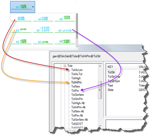
The entries under Acad/M  DimSet Tols, from top to bottom, correspond to the tolerance representations in the list, from left to right.
Like tolerances, the 12 representation in the list in the Fit Representations dialog box correspond to the first 11 entries under Acad/M > DimSet > Fits in the System Editor. The names of these entries begin with “Fit” (for example, FitNrm). The remaining entries refer to the alternative unit representation of fits; their names end with “-Alt.” For example, FitNrm -Alt, is the alternative unit representation of FitNrm.
System Editor entry mappings to fit representations
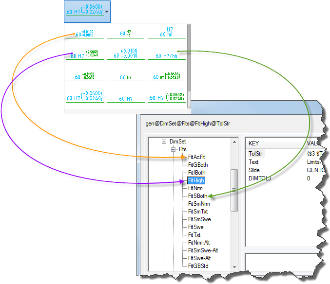
The entries under Acad/M DimSet Fits, from top to bottom, correspond to the tolerance representations in the Fit Representation list, from left to right.
The keys for the entries below “Fits” and “Tols”
The keys for the entries below “Fits” and “Tols” are the same, regardless of whether the entry is for a fit or a tolerance.
The keys for the entries below “Fits” and “Tols”
The keys for the entries below “Fits” and “Tols” are the same, regardless of whether the entry is for a fit or a tolerance.
The keys and the values they contain are:
|
Slide |
Contains the name of the graphic to show on the button face. This usually is the name of a slide file (*.sld) created with the MSLIDE command. |
|
|
Text |
Contains the text for the button caption. |
|
|
TolStr |
Contains the tolerance expression. Usually a combination of MTEXT format codes and special characters. |
|
|
TolStrSym |
Contains the tolerance expression to use for symmetric tolerances, where the tolerance is expressed in the form ±; 9.9999 . If this key does not exist, the system follows TolStr. |
|
|
TolStrOne |
Contains the tolerance expression to use for one-sided tolerances. If this key does not exist, the system follows TolStr. |
|
|
TolStrNeg |
Contains the tolerance expression to use for one-sided tolerances where the non-zero tolerance is negative. If this key does not exist, the system follows TolStrOne. |
|
|
DIM___ |
Contains a numeric value to use for setting an AutoCAD dimension variable that has the same name as this key. |
MTEXT format codes used in tolerance expressions
MTEXT format codes begin with a backslash (“\”) and end with a semicolon (“;”). Any set of MTEXT formatting characters can be used in tolerance expressions. The following list shows the formatting codes most commonly used in tolerance expressions.
|
\Hnnn; |
Changes the text height to nnn (absolute dimension). |
|
|
\Hnnnx; |
Changes the text height to nnn times the current text height. |
|
|
\Cnnn; |
Changes the color to nnn. |
|
|
\Fnnn; |
Changes the text font to nnn. |
|
|
\Annn; |
Sets the alignment value to nnn; valid values: 0, 1, 2 (bottom, center, top) |
|
|
\Snnnn^mmm; |
Stacks two texts on top of each other (text nnnn stacks on top of text mmm). |
|
|
{ .... } |
Formatting enclosed in parentheses applies only to the text within the parentheses. |
Special Characters used in tolerance expressions
The special characters most commonly used in tolerance expressions are:
|
$T |
Inserts a fit symbol; for example, "h7" or "js6". |
|
|
$X |
Specifies a second (bore) fit symbol to support two types of fit. If this is used, the "$T" is always the shaft fit. |
|
|
$P |
Denotes the upper deviation, without the sign. |
|
|
$+ |
Denotes the sign for the upper deviation. The appropriate sign ("+" or "-") is assigned based on the value of the deviation. |
|
|
$CP |
Denotes the sum of the dimension value and the upper deviation. Example: A dimension value of 30 units with an upper deviation of +0.010 is expressed as 30.010. |
|
|
$M |
Denotes the lower deviation, without the sign. |
|
|
$- |
Denotes the sign of the lower deviation. The appropriate sign ("+" or "-") is assigned based on the value of the deviation. |
|
|
$CM |
Denotes the sum of the dimension value and the lower deviation. Example: A dimension value of 30 units with a lower deviation of -0.030 is expressed as 29.970. |
|
|
$a_ |
Denotes the alternative units. They are: |
|
|
$aD - Dimension value. |
||
|
$aP - The upper deviation. |
||
|
$aM - The lower deviation. |
||
|
$aCP - The sum of the dimension and the upper deviation. |
||
|
$aCM - The sum of the dimension and the lower deviation. |
||
|
$2 |
Changes the color to the color assigned to small text (2.5 mm). |
|
|
$3 |
Changes the color to the color assigned to large text (3.5 mm). |
Examples
-
Example of an expression for a fit
$T {\H0.7x;$2 \A0;\S$+$P^$-$M;}
$T
Fit symbol, “lc3”in this case. No formatting information is appended to this special character, so it has the same height as the dimension text.
{
Opening brace, begins parentheses to apply format codes to the text within parentheses.
\H0.7x;
Sets the text height to 0.7 times the height of dimension text.
$2
Sets the text color to the color defined for small text.
\A0;
Sets the vertical alignment to bottom.
\S
Sets the upper deviation ($+$P) to be stacked on top of the lower ($-$M) deviation. The expression “\S$+$P^$-$M;” (using “\S” in combination with the caret character "^" and the semicolon character “;”) maps to the form \Snnnn^mmm;.
$+
The plus (+) sign in the upper deviation.
$P
The value of the upper deviation.
$-
The minus (-) sign in the lower deviation.
$M
The value of the lower deviation.
}
Closing brace, closes parentheses to apply format codes to the text between parentheses.
-
Example of an expression for an alternative unit representation of a fit
$T {\H0.71x;$2\S$+$P^$-$M;}{\H1.4x;[}$aD{\H0.71x;$2\S$+$aP^$-$aM;}{\H1.4x;]}
 Note: AutoCAD Mechanical toolset does not depend on AutoCAD to implement alternative units. Instead, it builds the alternative unit into the tolerance expression.
$T
Fit class; “lc3” in this case.
{ ... }
The deviations +.0000 and -.0018. See the previous example for an analysis of how the deviation is implemented.
{H\1.4x;[}
Sets text height to 1.4 times the height of dimension text and draws the left square bracket that marks the beginning of the alternative units.
$aD
The dimension value in alternative units; 238.43 mm in this case.
{ ... }
The deviations +0.0000mm and - 0.0457mm. See the previous example for an analysis of how the deviation is implemented.
{\H1.4x]}
Sets text height to 1.4 times the height of dimension text and draws the right square bracket that marks the end of the alternative units.