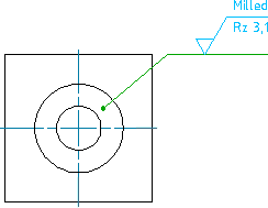
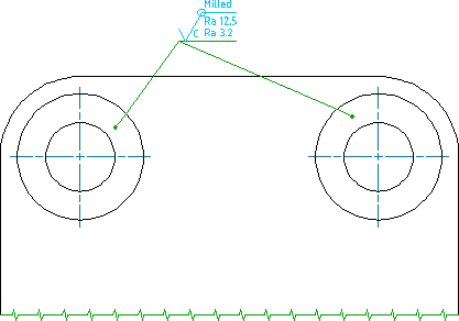
AutoCAD Mechanical toolset gives you the ability to create surface texture symbols that comply with the active drafting standard.
The complete list of supported standards appears at the bottom of this page.

Inserting a Symbol in a Drawing
You can place a surface texture symbol in the drawing by entering coordinate values, or using an object snap. You can position the symbol by itself or attached to a leader. The symbol can exist as a free-standing object or it can attach to an object in the drawing. When you attach a symbol, the symbol moves with the object whenever you move the object. If a symbol leader is attached to an object in the drawing and you want to attach it to another object, you must detach it first.
Surface Indication Leaders
AutoCAD Mechanical toolset provides command line options to create surface indication leaders. This enables symbol leaders to point to a surface rather than an edge. Using surface indication leaders you can indicate requirements using a top view rather than a side view.


Attach to Annotations
You can attach surface texture symbols to feature control frame symbols as shown in the in the illustration below.

Specifying Surface Texture Requirements
When the required surface texture must be produced by a particular method, indicate the method, in words, on a line added to the longer arm of the surface symbol. To include special characters such as the notation for the wave filter (λ), enter the corresponding Unicode character string (\U+03BB in this case) while entering text.
In some cases, drop-down lists enable you to pick surface texture requirements. You can customize these lists during configuration to eliminate surface texture requirements that you rarely use (and thereby reduce clutter) or add/edit entries that are unique to your drafting requirements.
Reuse Surface Texture Symbols from the Symbol Library
You can add any surface texture symbol you create to a Symbol Library. Thereafter you can insert surface texture symbols directly from the library, which can save you a considerable amount of time. The symbol library is stored in the drawing file, against the drafting standard.
Using a Surface Texture Symbol as a Majority Symbol
It is possible to set a surface texture symbol as a majority symbol. The symbol automatically indicates the state of surface texture symbols elsewhere in the drawing using a single collective indication. The majority symbol does not distinguish between different layouts. If you delete a block that contains a surface texture symbol that is counted in a majority symbol, the majority symbol does not update until you purge the block.
Supported Drafting Standards
| Standard/Revision | Surface Extension Lines | Surface Indication Leaders | Majority Symbol |
|---|---|---|---|
| ASME Y14.36M (2018) | Yes | Yes | |
| ASME Y14.36M (1996) | Yes | ||
| BS EN ISO 1302 (2002) | Yes | ||
| BS 308 (1990) | Yes | ||
| CSN 01 3144 (1981) | Yes | Yes | |
| DIN EN ISO 1302 (2002) | Yes | Yes | Yes |
| DIN ISO 1302 (1992) | Yes | Yes | |
| GB/T 131 (2006) | Yes | Yes | Yes |
| GB/T 131 (1993) | Yes | Yes | |
| ISO 21920-1 (2021(E)) | Yes | Yes | |
| ISO 1302 (2002(E)) | Yes | Yes | Yes |
| ISO 1302 (1978) | Yes | Yes | |
| JIS B 0031 (2003) | Yes | Yes | Yes |
| JIS B 0031 (1994) | Yes | Yes | |
| GOST 2.309-73 (Rev 3) | Yes | Yes | |
| GOST 2.309-73 | Yes | Yes |