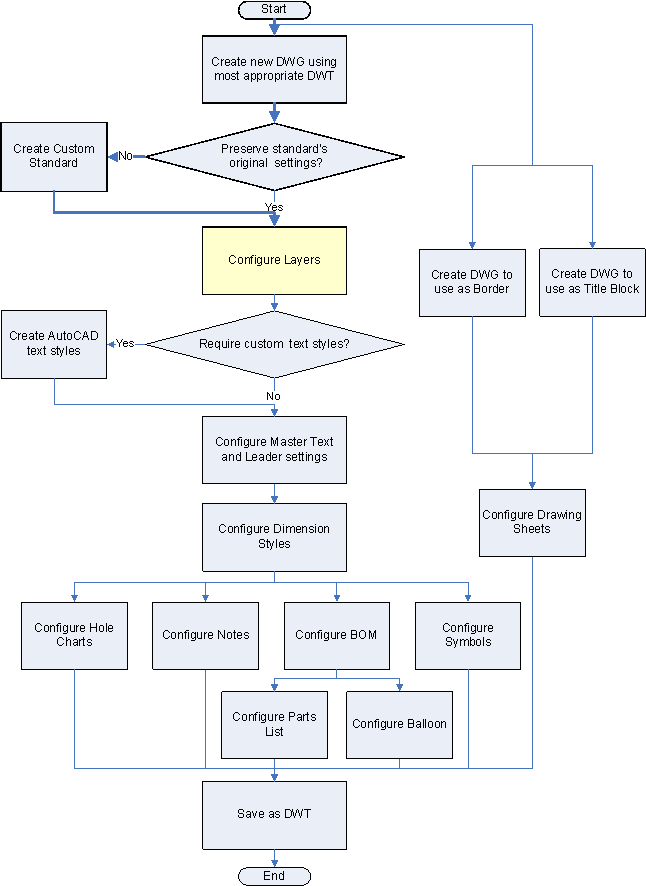
Where am I in the flowchart?

Layers
Company XYZ has been using AutoCAD for many years and has established guidelines on the usage of layers. They require AutoCAD Mechanical toolset layers to follow the same guidelines.
Layer Renaming
They change the “AM_” naming convention to match the names they use currently. In addition, some of the layers have different color, linetype, and lineweight properties, requiring modification to the defaults.
|
ACM Layer Name |
Company Layer Name |
Color |
Linetype |
Lineweight |
|---|---|---|---|---|
|
AM_0 |
CONTOUR_LINES |
White (7) |
Continuous |
0.50mm |
|
AM_3 |
HIDDEN |
Magenta (6) |
Hidden (AM_ISO02W050) |
0.25mm |
|
AM_4 |
AUXILIARY |
Green (3) |
Continuous |
0.25mm |
|
AM_5 |
DIMENSIONS |
Red (1) |
Continuous |
0.25mm |
|
AM_6 |
TEXT |
Yellow (2) |
Continuous |
0.35mm |
|
AM_7 |
CENTERLINES |
Cyan (4) |
Center Lines (AM_ISO08W050) |
0.25mm |
|
AM_8 |
HATCHING |
Red (1) |
Continuous |
0.25mm |
|
AM_CL |
CONSTR_LINES |
Blue (1) |
Continuous |
0.25mm |
Layers for Standard Parts
The company requires that standard parts not be created on special standard part layers (the default), but on the previously renamed layers instead.
Layer Creation
Company XYZ want symbols such as balloons, welding, and surface finish symbols, placed on a layer dedicated for symbols rather than the same layer as dimensions (AM_5). This modification requires them to create a layer called SYMBOLS and map the symbols to the new layer.
|
ACM Layer Name |
Company Layer Name |
Color |
Linetype |
Lineweight |
|---|---|---|---|---|
|
AM_5 |
SYMBOLS |
Red (1) |
Continuous |
0.35mm |