Adds or removes leaders and leader segments to/from a symbol.
Find Find
Find
FindSummary
This command does not work on symbols such as the GOST dead joint symbol, where the drafting standard prohibits the addition or removal of leaders and leader segments.
List of Prompts
The following prompts are displayed:
Add

Adds a leader to an existing symbol.
- Select symbol to add leader to
- Specifies the symbol to add the leader to.
- Select object to attach
- Specifies the object to attach the leader to. To place the leader without attaching it to anything, click the position you want to place the arrowhead of the leader. If you select an arc, circle, spline, or ellipse, you do not need to specify the leader start point. The program derives the leader start point by making the first leader segment perpendicular to the attached object. If you select a line, or do not select an object, the program prompts you to specify the leader start point. Note: The prompts that are displayed from this point onwards depend on the type of object you select.
- Start point
- Specifies the position of the leader start point.
- Next point
- Specifies the location of the next vertex of the leader.
- Surface
- Adds a surface indication leader (an additional arrowhead, leader and reference line) to the symbol, to enable you to point to a surface rather than an edge. This option is not displayed if:
- The selected symbol is not a feature control frame symbol, datum identifier symbol or a surface texture symbol.
- The revision of the standard controlling the selected symbol does not permit surface indication leaders.
- The standard does not permit surface indication leaders, given the symbol's current configuration. For example:
- Surface texture symbols that already have a primary leader.
- Feature control frame and datum identifier symbols that are already attached to an object.
- Feature control frame symbols that have multiple primary leaders.
- Feature control frame symbols that have a primary leader and a secondary leader.
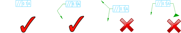
Note: For standards that support orthogonal leaders, this command forces the first leader segment to be perpendicular to the attached object. It also forces subsequent leader segments to be horizontal or vertical. To override this restriction, press the Toggle Symbol Leader Orthogonal Mode key (SHIFT + F, by default) as you move the cursor. - Edge
- Enables you to return to the previous prompt (edge selection mode), if you select the "Surface" option by mistake.
- Auto route
- Automatically routes the leader from the last specified point to the most logical connection point on the symbol.
Remove

Deletes leaders or leader segments.
- Select leader node or leader segment
- Specifies the node or a leader segment to remove. If you select an internal leader segment, all the following leader segments are deleted as well. If you select a node, at least two neighboring leader segments are deleted.