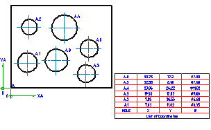
Creates coordinate dimensions for holes in a work piece, dimensions the size of those holes, and generates a hole chart for that work piece.
Find
The attributes, order, and increment of the coordinate reference numbers depends on the standard you have selected as the current drafting standard. In the ANSI standard, this command creates a hole table in addition to a hole chart.
List of Prompts
The following prompts are displayed.
- Insertion point for origin
- Specifies the location for the origin for the coordinates to use for the hole chart.
- Polar
- Uses polar coordinates to specify the location of holes.
- Cartesian
- Uses Cartesian coordinates to specify the location of holes.
- Rotation angle
- Specifies how far to rotate the coordinates with respect to the current UCS.
- Select holes
- Specifies the holes, circles and circular edges to list in the hole chart.
- Block
- Restricts selection to holes within block references.
- Select block reference - Specifies the block reference that contains the holes to include in the hole chart.
- Select nested objects - Specifies the holes, circles and circular edges to list in the hole chart. You can only select objects that belong to the selected block reference.
- Point
- Adds a point to the hole chart as a hole of unknown diameter
- Insertion point of hole chart
- Specifies where to insert the hole chart.
- Dialog
- Displays the Hole Chart dialog box.