In this exercise, you will project multi-view blocks and 3D polylines from plan view onto section views.
A variety of AutoCAD and Autodesk Civil 3D objects can be projected into a section view. However, linear objects, such as 3D polylines and feature lines, are represented as a marker that indicates the point location where the object crosses the sample line in plan.
Project objects onto multiple section views
- Open
Section-Project-Objects.dwg, which is located in the
tutorials drawings folder.
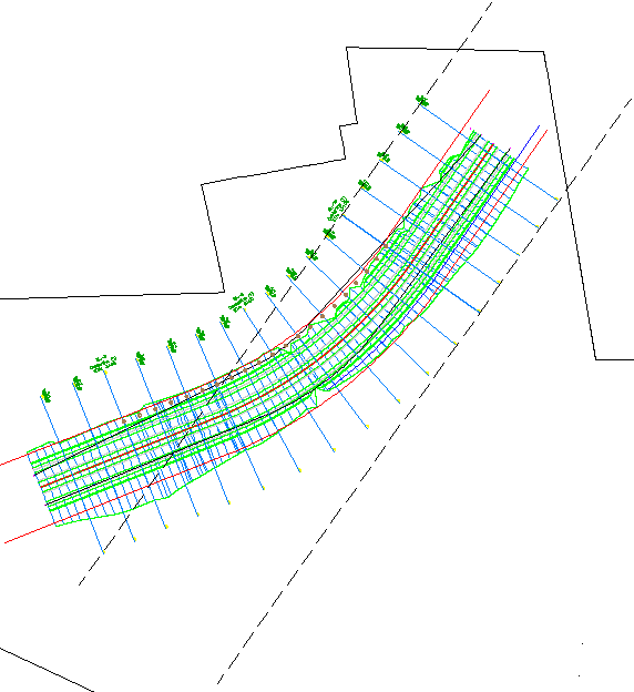
A proposed corridor and a series of section views are displayed in two viewports in the drawing. Along the corridor, several other objects are visible:
- Red polylines on either side of the corridor represent the corridor right-of-way.
- A blue polyline along the right side of the corridor represents a fence.
- AutoCAD blocks that represent utility poles are displayed along the right side of the corridor.
- Multi-view blocks that represent a line of trees are displayed along the left side of the corridor.
- Click
tab
 panel drop-down Find.
- In the top viewport, select one of the section views.
The Project Objects To Multiple Section Views dialog box is displayed. Under Projection Rules, you may specify the proximity area for non-linear objects to be projected.
- Under
Projection Rules, select
By Distance.
This option specifies that objects that are a specified distance before or after a sample line are projected.
- For Distance Before and Distance After, enter 50.
- In the table, under Name, clear all check boxes except Blocks and 3D Polylines.
- In the
Blocks row, specify the following parameters:
- Style: Projection Without Exaggeration
- Elevation Options:
SurfaceCorridor - (1) Surface - (1)
- Label Style: Offset and Elevation
- In the
Blocks and
3D Polylines rows, specify the following parameters:
- Style: Projection Without Exaggeration
- Elevation Options:
SurfaceEG
- Label Style: Offset and Elevation
- Click
OK.
The 3D polylines are displayed on the section views. The labels annotate the offset and elevation at which each object is projected.
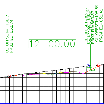
- In the bottom viewport, zoom in to the area between stations 7+00.00 and 13+00.00.
At sample lines SL-07, SL-08, SL-12, and SL-13, examine the proximity of the utility pole blocks. You specified a distance of 50 feet as the projection distance, which means that specified objects that are within 50 feet of a sample line will be projected.
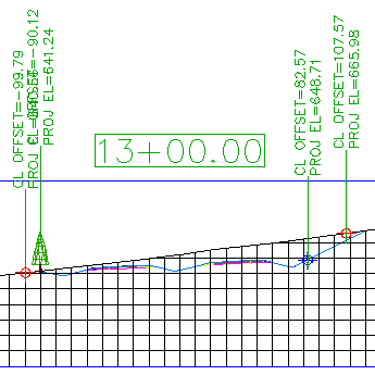
In the top viewport, notice that a utility pole block does not appear in section view 13+00.00. This section view does not display a utility pole block because one does not appear within 50 feet before or after the sample line.
Project objects onto a single section view
- In the top viewport, pan and zoom until you see section 13+00.00.
- Click
tab panel drop-down Find.
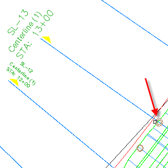
- In the bottom viewport, select the multi-view block that represents a tree at station 13+00.
- Press Enter.
- In the top viewport, click section view 13+00.
- In the
Project Objects To Section View dialog box, click
 <Set All> in each column to specify the following parameters:
- Style: Projection Without Exaggeration
- Elevation Options:
SurfaceEG
- Label Style: Offset and Elevation
- Click
OK.
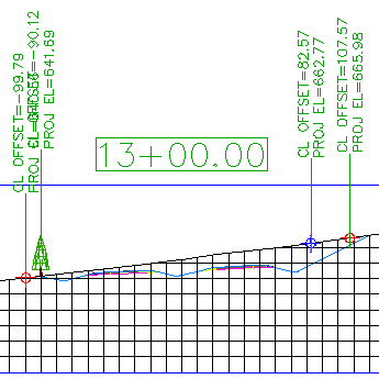
The block is displayed on the section view.
Edit the elevation of a projected object
- In the top viewport, click the blue marker that indicates the elevation of the fence.
When you select the marker in the section view, notice that the blue 3D polyline in plan is highlighted.
- Click the
 grip. Drag the grip down to change the elevation of the 3D polyline.
When you click to place the grip, you are notified that the elevation option for the polyline will be changed to manual. This option enables you to specify an elevation value for an object at the current station. The elevation value is applied in the current section view, but the value does not affect the object in plan view.
- In the task dialog box, click No.
- Press Esc.
- Select section view 13+00. Right-click. Click
Section View Properties.
The Projections tab is displayed on the Section View Properties dialog box. You can use the controls on this tab to change the parameters you used when you projected objects onto the section view.
Note:Like other Autodesk Civil 3D labels, label parameters are changed by selecting the desired label, and then using the Labels contextual tab on the ribbon.
- In the
Section View Properties dialog box, on the
Projections tab, under
 3D Polylines, select the
3D Polyline- 23 row.
3D Polylines, select the
3D Polyline- 23 row.
When you select the row, notice that the corresponding object is highlighted in both plan and section views.
- In the
Elevation Options column, change the value to
 SurfaceCorridor - (1) Surface - (1).
- Repeat Steps 6 and 7 to change the elevation of
 Multi View BlocksEastern White Pine- 21 to reference
Corridor - (1) Surface - (1).
Multi View BlocksEastern White Pine- 21 to reference
Corridor - (1) Surface - (1).
- Click
OK.
In the section view, notice that the fence marker and tree are now at the corridor surface elevation.
In the following steps, you will change the elevation of the tree and fence marker so that they reflect the elevation of the corridor surface.
Project an object that is at a different station
- In the bottom viewport, pan until you can see sample lines SL-3 and SL-8.
- Click
tab panel drop-down Find.
- In the bottom viewport, select the blocks that represents trees at SL-3 and SL-8.
- Press Enter.
- In the top viewport, click section view 13+00.
- In the
Project Objects To Section View dialog box, click
<Set All> in each column to specify the following parameters:
- Style: Projection Without Exaggeration
- Elevation Options:
SurfaceCorridor - (1) Surface - (1)
- Label Style: Offset Elevation
- Click
OK.
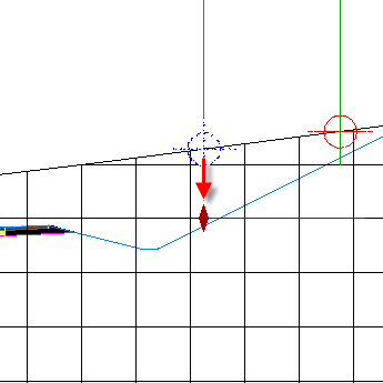
The tree is displayed on the section view. Two things are evident:
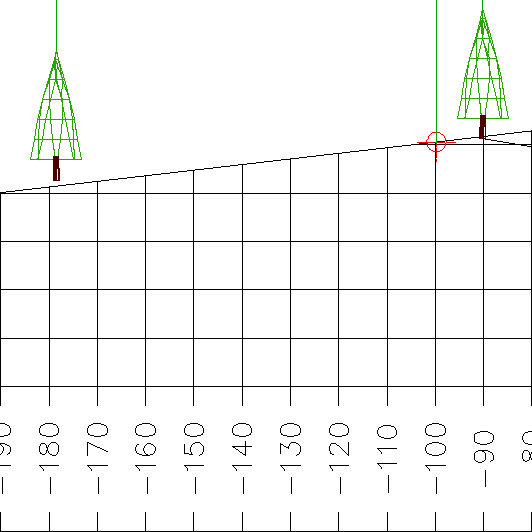
- Only one of the blocks was projected onto the section view. Objects in a site can be projected to a section view only if the object falls within the perpendicular swath width at the specified sample line. The block at SL-3 was not projected onto the section view because the block offset value is greater than the perpendicular swath that is encompassed by SL-13. The black, dashed lines in the following image illustrate the sample line extents at SL-13.
- The block from SL-8 is shown at an elevation that appears to be above the surface. The block is projected at the surface elevation where it is actually located, and not at the surface elevation at the current sample line. However, the offset value that is displayed in the label reflects the object’s offset value at the current sample line.
- Only one of the blocks was projected onto the section view. Objects in a site can be projected to a section view only if the object falls within the perpendicular swath width at the specified sample line. The block at SL-3 was not projected onto the section view because the block offset value is greater than the perpendicular swath that is encompassed by SL-13. The black, dashed lines in the following image illustrate the sample line extents at SL-13.
Further exploration: Examine the style settings that are available for projected objects. Projected object styles are located in
Toolspace, on the
Settings tab, in the
GeneralMultipurpose StylesProjection Styles collection. Label styles for projected objects are located in
Toolspace, on the
Settings tab, in the
Section ViewLabel StylesProjection collection.
To continue this tutorial, go to Exercise 2: Adding a Section View Grade Label.