In this exercise, you will build the box portion of the vault. You will use projection geometry and constraints to link the box to the frame so that a single set of dimensions can control both.
This exercise continues from Exercise 2: Defining the Vault Top Section Geometry.
- Continue from the previous exercise in the
Part Builder environment. Click
View tab
 Views panel SW Isometric. Next you will create a reference work plane at the bottom of the frame. This view makes it easier to perform the next few steps.
- In the Content Builder window, right-click Work Planes, and then click Add Work Plane. The Create Work Plane dialog box is displayed.
- Click Reference then enter Top of Box for Name. Click OK. You are prompted for a modifier.
- When prompted for modifier, select the 3D frame object.
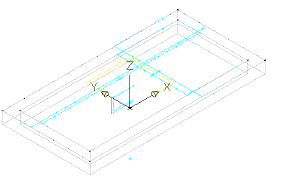
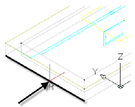
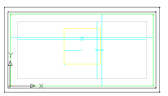
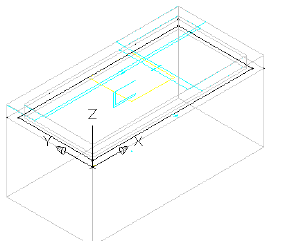
A new yellow rectangle is displayed representing the reference plane at the bottom of the frame (also top of box). This reference plane is attached to the modifier and moves if the frame thickness is adjusted.
When prompted for the work plane, select the yellow rectangle at the top of the frame object (this represents the top plane).
When prompted for the reference work plane, click along the lower edge of the frame object.
- Right-click
Top of Box and then click
Set View. Next, click
View tab Views panel SW Isometric.
This sets the working plane to Top of Box and then returns the drawing to its original view.
- Right-click
Top of BoxAdd GeometryProjected Geometry. You are prompted for a modifier.
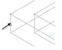
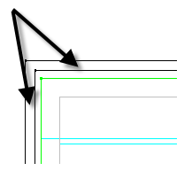
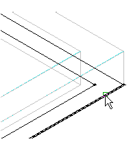
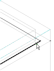
- Click the 3D frame object. When prompted for the geometry to project, click one of the lower edges. The line highlights in red when the cursor is in the correct position. Repeat this process for the three remaining lower edges.
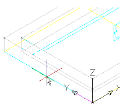
This creates geometry that is linked to the lower edge of the frame extrusion. This is a key relationship in building the box section below the frame so that it is aligned with the frame. The projected geometry is displayed in green.
- Set the visibility of all geometry and profiles in the Rim work plane to off. Right-click Top of Box and then click Set View. Objects in the Rim work plane are turned off so that you do not snap to them or use them inadvertently.
- Right-click
Top of BoxAdd ProfileRectangular. You are prompted for rectangle points.
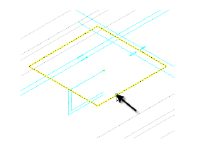
- Click two points to create a rectangle that is outside of the current geometry. In Content Builder, change the name Rectangular Profile to Outer Wall. A rectangular profile is drawn.
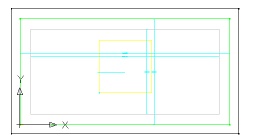
- Draw a second rectangular profile within the first. Change its name to Inner Wall. There are now two rectangular profiles.
- Right-click
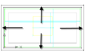
Top of BoxAdd ConstraintsEqual Distance. Click the left side of the outer rectangle, then the left side of the inner rectangle. Then click the top side of the outer rectangle and the top side of the inner rectangle. The distance between the outer wall and inner wall on the left side is set to always match the distance between the outer wall and inner wall on the top side.
- Repeat this procedure, first clicking the top pair of lines then clicking the right pair. Continue around the rectangle in a clockwise direction, finishing up by setting the right side equal to the bottom side.
All sides are now equal. With these constraints in place, you can change the thickness of one side and the changes affect all sides.
- Right-click
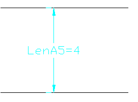
Top of BoxAdd DimensionPerpendicular Distance. Click a line on the inner rectangle then the corresponding parallel line on the outer rectangle. Click either of the lines once again to set a perpendicular reference object. Pick a point between the two lines for the dimension position and enter 4 for the dimension value. A new dimension named LenA5 is created. This single dimension sets the wall thickness of the box. Because of the equal distance constraints established in the step above, this dimension controls all four sides.
- Right-click
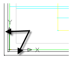
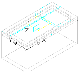
Top of BoxAdd ConstraintCoincident. Click the black point at the top left corner of the outer box, then click the green projected point at the top left corner of the frame.
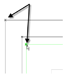
The black point is moved to be coincident with the green point. Because of constraints, the top and left sides of both rectangles are moved and the 4" distance between the inner and outer walls is maintained.
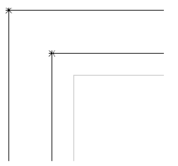
- Repeat this procedure for all four corners. You may need to use Shift+Space to select the green point. The Top of Box geometry is linked to the green projected geometry, which is linked to the extrusion modifier projected from the Rim work plane. With these relationships, the geometry of the entire vault can be controlled with a few parameters.
- Right-click Model Parameter and then click Edit. Change the Equation for LenA5 to Wth. Change the value for Wth to 4. Wall thickness (Wth) is one of the size parameters that is built in to this part type.
- Click
View tab Views panel SW Isometric. Right-click
Modifiers and then click
Add Extrusion. You are prompted to select a profile.
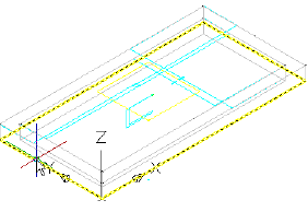
- Click the outer rectangle. Enter 48 for
Distance and check the box next to Flip. Click
OK.
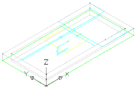
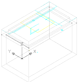
An extrusion is created that extends downward 48 inches.
- Change the name of the new extrusion modifier to Box Outside. Repeat these steps for the inner rectangle using a distance of 44 and a name of Box Inside.
The inner extrusion stops 4 inches shy of the outer extrusion, creating a 4-inch thick floor.
- Right-click Modifiers and then click Add Boolean Subtract. Click the outer extrusion, then the inner extrusion. Press Enter. Name the new modifier Box.
- Right-click
Size Parameters and then click
Edit Values. Change to the following values:
- SBSL = 84
- SBSW = 48
- SFL = 72
- SFW = 36
Click the Update Model button in the Edit Part Sizes dialog box toolbar, and then click OK. Note the change to the model. The model updates according to the size parameter changes.
- Click Save Part Family. Stay in the Part Builder environment for the next exercise.
To continue this tutorial, go to Exercise 4: Finalizing the Part.