In this exercise, you will cause the surface to triangulate along a linear feature.
Breaklines are used to define surface features and to force triangulation along the breakline. Surfaces do not triangulate across breaklines, creating more accurate TIN surface models.
In this exercise, you will create breaklines along the edge of pavement for an existing road. Breaking the surface along features produces a more accurate surface rendering.
This exercise continues from Exercise 2: Adding Point Data to a Surface.
Display the source polylines and change the surface style
- Click Home tab
 Layers panel Layer drop-down. Next to the _EG_BREAKLINES layer, click
  .
. The 3D polylines that represent the edge of pavement (EP) of an existing road are displayed on the east side of the site.
Note:The EP polylines were included in the drawing template you used in Exercise 1: Creating a TIN Surface.
- Select the surface. Right-click. Click Surface Properties.
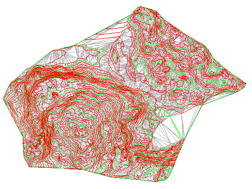
- In the Surface Properties dialog box, on the Information tab, for Surface Style, select Contours and Triangles. Click OK.
The surface now shows contours and triangles that illustrate the EG surface triangulation.
This exercise uses the drawing you created in the previous exercises, or you can open Surface-1B.dwg from the tutorials drawings folder.
Create breaklines from the polylines
- In Toolspace, on the Prospector tab, expand the
 SurfacesEG
 Definition collections. Right-click
  Breaklines. Click Add.
 - In the Add Breaklines dialog box, for Description, enter Edge of pavement - existing road. Use the default values for the other fields. Click OK.
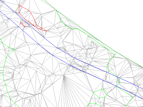
- The Select Objects prompt becomes active. While in this command, use the Zoom and Pan commands to locate the two blue 3D polylines on the east side of the site.
Zoom in close so you can see that the triangles cross over the polylines.
- Select the polylines. Press Enter.
The surface triangulation is modified. The edge of pavement breaklines are applied, and the TIN surface is adjusted along the breakline edges, modifying the surface triangulation.
- Click View tab Navigate 2D panel Extents.
The drawing window zooms to the extents of the surface. With the breakline data added, the layer that contained the source data for the breaklines can be frozen.
- Click Home tab Layers panel Layer drop-down. Next to the EG_BREAKLINES layer, click
 .
.
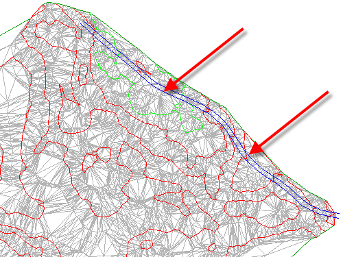
Further exploration: Notice that, along some portions of the polylines, the surface triangulation incorrectly crosses the breakline. This happened because the surface contours also act as breaklines. The new breaklines are not added because the contours are already acting as breaklines, and the current surface setting does not allow more than one breakline to affect the surface at a given point. To override this behavior, you can perform any of the following tasks:
- Build the surface with contours and breaklines: In the Surface Properties dialog box, on the Definition tab, expand the Build collection. Set Allow Crossing Breaklines to Yes, and then set Elevation to Use to Use Last Breakline Elevation at Intersection.
- Modify the surface: Use the DeleteSurfacePoint command to delete surface points that are located exactly on the polylines.
- Modify the polylines: Add a vertex to the polylines at each location where it crosses a surface contour.
To continue this tutorial, go to Exercise 4: Adding an Outer Boundary to a Surface.