3D Shape Menu Settings
Basics Tab
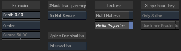
Depth field
Displays the level of depth (thus extruding the selection, making it three dimensional). Editable.
Depth Mode box
Select where the extruded geometry is positioned along the Z axis. Select Custom to set the distance from front to back manually.
Depth Centre field
Displays the position of the extruded geometry along the Z axis, as a percentage. Editable if Custom is selected in the Depth Mode box.
GMask Transparency box
Select how the transparency of an attached GMask is rendered.
| Select: | To: |
|---|---|
| For 3D Shape Only | Render the GMask as if it were linked to the 3D Shape object only. In this case, the GMask blend mode is automatically set to 2 Intersect 1 (Inside) for optimal blending. |
| Render | Render the GMask globally in the Action scene. In this case, the GMask blend mode is automatically set to Add for optimal blending. |
| Do Not Render | Not render the GMask in the scene. In this case, certain GMask menu settings are hidden, such as Transparency, Intensity, Smoothing and Blending. |
Spline Combination box
Select how multiple GMask splines attached to the 3D Shape object are combined.
| Option: | Combination Pattern: |
|---|---|
| Intersection | Splines with the Hole button selected (in the GMask menu) are always rendered as a hole; other splines are rendered according to their relative position. Where two or more splines overlap, these rules apply: An even number of overlaps are rendered as a hole; whereas an odd number are rendered as filled. |
| Union | Splines with the Hole button selected (in the GMask menu) are always rendered as a hole; other splines are rendered filled, except for their intersection with holes. |
| Priority | Splines are rendered according to their status (hole or filled, depending on the state of the Hole button), and the GMask Priority list determines the proper combination pattern. |
Multi Material button
Enable to create an Object Group node for each of the front, back, and extrude of the 3D object. You can then attach a different texture map to apply to the different surfaces.
Media Projection button
Enable to automatically add a Diffuse (and Axis) node to the 3D Shape node with its mapping type set to Projection.
Shape Boundary box
Select how an attached GMask's softness is extruded. Available when an attached GMask is closed, and has an inner or outer softness.
| Select: | To extrude: |
|---|---|
| Only Spline | Just the original curve. |
| Only Softness | Just the geometry between the softness. |
| Spline And Softness | Everything inside the outer softness. Set automatically when a softness is added. |
Use Inner Softness button
Enable to include the inner softness when using the Spline And Softness option in the Shape Boundary box. Disable if tessellation issues occur when using inner and outer softnesses.
Profile Tab
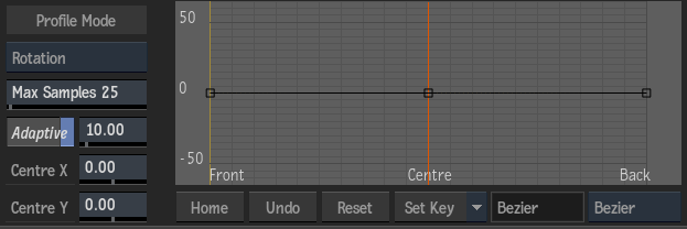
Profile Type box
Select which profile curve to display. Different settings may appear depending on the type selected.
Adaptive button
Enable to extrude based on an adaptive subdivision, adding smaller segments where there is a higher curvature. When disabled, the depth is divided into Max Samples slices of exactly the same size.
Tolerance field
Displays the point at which the extrusion is subdivided. Editable.
Samples field
Displays the maximum number of extrusion samples applied to the non-flat curves. Editable.
Centre X field
Displays the centre along the X axis that the scale and rotation curves use. You can also adjust the centre settings in the image window by dragging the crosshair. Editable.
Centre Y field
Displays the centre along the Y axis that the scale and rotation curves use. You can also adjust the centre settings in the image window by dragging the crosshair. Editable.
Parametric Angle field
Displays the slope of the beveling. Editable.
Parametric Position field
Displays the relative position of the start of the beveling. Editable.
Parametric Curvature field
Displays the roundness or curvature of the beveling. Editable.
Curvature Type box
Select the type of curvature to apply to the parametric curve.
Profile Curve
Displays the selected profile curve (bevel, scale, or rotation). Move and add points to the curve, as well as adjust the tangent handles to produce different effects with the extruded geometry. If you select a Parametric profile type, a separate read-only curve is displayed.
Parametric Bevel Curve
Read-only display of the parametric profile curve, based on the profile settings.
Home button
Resets the selected curve viewer to show the whole curve.
Undo button
Undoes the last operation for the selected curve viewer.
Reset button
Resets the selected curve viewer to the default curve.
Keyframe Option box
Select an option for working with keyframes in the profile curve.
Interpolation Status field
Displays the interpolation type for the selected area of the curve. Non-editable.
Interpolation Type box
Select an interpolation type to define the shape of the profile curve between keyframes.
Geometry and UV Map Tabs
The settings in the Geometry and UV Map tabs are the same as for the Geom node.