Position Mapping
A position map (sometimes called a world position pass), is an image where each pixel's R, G, B colour values represent the x, y, z coordinates of the corresponding vertex, in 3D world space. In Action, a position map works as a type of 3D displacement, that is, it displaces every pixel in that image to the actual location in space of the vertex it represents, allowing you to:
- Establish depth, position, and scaling in images, for compositing and creative purposes.
- Relight your scene.
- Create stereo objects.
- Creatively transfer the position of one object onto another object.
A typical workflow would be to import (from a 3D application) the beauty pass, the position pass (as a 16-bit floating point OpenEXR clip), the normal pass, and the FBX camera that rendered the scene. Then, apply the position and the normal map to the beauty pass image surface, and set the scale of the position map so that it aligns properly with the 3D camera frustum.
When looked from the original camera POV, your scene looks just like the rendered image. But since pixels are accurately located in space relative to the original 3D scene with the attached position map, you can correctly position 2D layers in the same perspective as objects of the 3D scene.
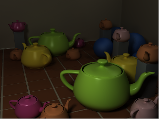 Beauty Pass | 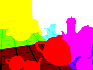 Position Map | 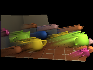 Action scene with camera orbited |
You can use position maps generated by 3D applications or Action itself (Position is available as an output type in the Output menu).
To add a position map:
In the schematic, select the surface to which you want to apply the position map.
Click Media.
In the Media menu, select the media you want to use for the position map.
Do one of the following:
- Drag the Position Map node from the node bin and place it in the schematic.
- Drag the Position Map node from the node bin and place it where you want it in Result view.
- Double-click the Position Map node. You do not need to be in Schematic view to add a node in this manner.
The position object is added to the schematic with its own parent axis. The new axis is the child of the selected surface. In Schematic view, the number in brackets next to the name of the Position node indicates the media used for the position map.
To specify different media as the position map source, select the media in the Media menu, then click Apply.
Note: If you accessed Action as a Timeline FX, you are limited to one front/matte media, and therefore may not get the desired result. In this case, you can access Action from Batch or Batch FX, or from the Tools tab.Double-click the Position node in the schematic, or follow the tab population rules for the Object menu.
The Position menu appears.