Displacement Mapping
Use displacement mapping to create a 3D model from a 2D surface. The values of a selected colour channel in the displacement source clip are used to create a displacement map. Displacement mapping uses the media’s matte clip, so you can turn the matte on or off to get the desired effect.
You have the choice of applying hardware or software displacement mapping. Hardware displacement mapping is GPU-accelerated and allows you to create a normal map if none exists. Software displacement mapping displaces the pixels of the surface along the positive or negative X, Y, and/or Z axes. Hardware Displacement is faster than software displacement, especially when using low resolution values in an image surface (high polygon count).
To add a displacement map:
In the schematic, select the surface or 3D geometry to which you want to apply the displacement.
Click Media.
In the Media menu, select the media you want to use for the displacement.
Do one of the following:
- Drag the Displace Map node from the node bin and place it in the schematic.
- Drag the Displace Map node from the node bin and place it where you want it in Result view.
- Double-click the Displace Map node. You do not need to be in Schematic view to add a node in this manner.
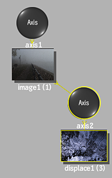
The displace object is added to the schematic with its own parent axis. The new axis is the child of the selected surface or geometry. In Schematic view, the number in brackets next to the name of the displace node indicates the media used for the displacement.
To specify different media as the source, select the media in the Media menu, then click Apply, or use the Read File tab to manage the texture media (see Working With Textures in Map Nodes).
Note: If you accessed Action as a Timeline FX, you are limited to one front/matte media, and therefore may not get the desired result. In this case, you can access Action from Batch or Batch FX, or from the Tools tab.Double-click the Displace node in the schematic, or follow the tab population rules for the Object menu (see Populating Menu Tabs of Selected Objects).
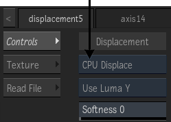
The Displacement menu appears. You can choose between Hardware Displacement or Software Displacement using the Displacement Type box.