Thermal Residual Stresses
Consider the effects of thermal residual stresses on unidirectional composites.
**Currently, thermal residual stresses can only be computed for unidirectional composite materials, not woven composite materials.
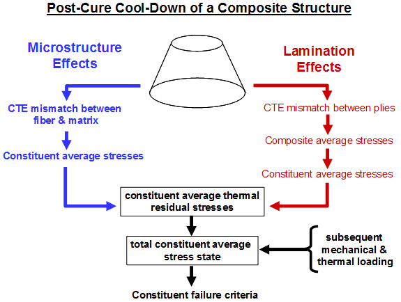
Microstructure Effects
At room temperature T=Tamb, the fiber and matrix constituents of an isolated, unloaded, unconstrained, unidirectional composite ply already have a nonzero stress state. This is due to post-cure cooling of the composite material from the cure temperature T=Tcure to ambient temperature T=Tamb. In an isolated composite ply, these thermal residual stresses are caused solely by differences in the coefficients of thermal expansion of the matrix and fiber constituents. Typically, during post-cure cooling of a fiber-reinforced composite ply, the matrix constituent attempts to shrink more than the fiber constituent. Thus, the matrix constituent exhibits tensile thermal residual stresses and the fiber constituent exhibits compressive thermal residual stresses. However, the composite average stress state is zero. These constituent thermal residual stresses contribute to the total constituent stress states during any subsequent thermomechanical loading of the composite ply and thus influence the load at which constituent failure occurs.
Lamination Effects
When a composite ply is embedded in a laminate that undergoes a post-cure cool down, additional thermal residual stresses are induced in the composite ply. This is due to differences in thermal coefficients of expansion between the ply in question and its neighboring plies. Unlike the case of an isolated composite ply, this type of inter-ply action causes the composite average stress state at the ply level to be non-zero, i.e., the ply develops composite average thermal residual stresses. These stresses can be decomposed into fiber and matrix average thermal residual stresses which contribute to the total fiber and matrix average stress states during subsequent thermomechanical loading. Thus, the stresses influence the loads at which constituent failure occurs.
These two sources of thermal residual stresses at the constituent material level are shown schematically below. It is shown that constituent thermal residual stresses add to the constituent stresses produced by the normal externally applied mechanical and thermal loading of the structure.
Calculation of Thermal Residual Stresses in Helius PFA
Equations 32a-c list the linearized, thermomechanical constitutive relations (secant formulation) for a unidirectional composite material, the matrix constituent material and the fiber constituent material.
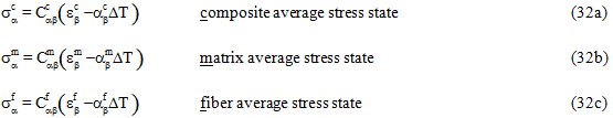
In Eq. 32a, the total composite strain state at a point ( ) is provided directly by the structural finite code, whereas in Eqs. 32b and 32c, the total constituent strain states at a point (
 and
and  ) are determined using the MCT decomposition of . For temperature-dependent composite materials, both the stiffnesses (
 ,
,  ,
,  ) and the coefficients of thermal expansion (
 ,
,  ,
,  ) are dependent on the current temperature T and the current failure state of the fiber and matrix constituent materials. For temperature-independent composite materials, both the stiffnesses (, , ) and coefficients of thermal expansion (, , ) are dependent only on the current failure state of the fiber and matrix constituent materials.
In Eqs. 32, one would normally envision the temperature change ΔT to be the difference between the current temperature T of the composite and the stress free temperature Tsf of the composite, i.e., ΔT = T - Tsf. However, the actual expression Helius PFA uses to compute ΔT depends upon whether or not you wish to account for thermal residual stresses that accumulate during post-cure cool down of the composite. This feature is toggled on and off for any composite material by the integer value of the appropriate user material constant.
Thermal Residual Stresses Turned 'OFF'
If the thermal residual stress feature is turned 'OFF', thermal residual stresses are not included in the response of the composite material during the simulation. In this case, the stress free temperature of the composite material defaults to Tsf =0°, and the temperature change used in Eqs. 32 is simply computed as ΔT = T - Tsf = T. Several points should be emphasized for the case where thermal residual stress calculation is turned 'OFF'.
- The stress free temperature Tsf defaults to 0° even if the composite material data file (mdata file) explicitly defines a non-zero stress free temperature. 21 Regardless of the system of units employed by the finite element model, the current temperature T completely defines the temperature change ΔT used in Eqs. 32.
- For composite materials characterized at multiple temperatures, the current temperature T is used to interpolate the material properties that appear in Eqs. 32. Consequently, if thermal residual stresses are ignored for a composite material, it is recommended that a single-temperature characterization (i.e., a single-temperature mdata file) be used for the composite material in question.
To summarize for the case where thermal residual stresses are ignored, the current temperature T influences Eqs. 32 in two different ways:
- T is used to define ΔT via ΔT=T.
- T is used to interpolate the current values of the material properties , , , , , and .
Thermal Residual Stresses Turned 'ON'
If the thermal residual stress calculation feature is turned 'ON', thermal residual stresses are explicitly included in the response of the composite material during the simulation. In this case, the stress free temperature Tsf of the composite material is read from the MCT composite material database file (mdata file) where Tsf is understood to be synonymous with the cure temperature Tcure of the material. If the stress free temperature Tsf of the material is not explicitly defined in the mdata file, Helius PFA produces an error message indicating that the stress free temperature must be defined.
When the thermal residual stress calculation feature is turned 'ON', there are two methods for calculating the temperature change used in Eqs. 32, depending on whether or not the material properties for the current temperature are used (default), or if a unique set of material properties are specified.
Current Environment
For the default case in which the current properties are used, the temperature change is computed as follows:

In Eq. 33a, Tamb is the ambient temperature which is understood to be 72.5 °F, 22.5 °C or 295.65 °K depending upon the system of units used in the model. T is the current temperature, and Tsf is the stress free temperature.
When the current temperature T > Tamb, Eq. 33a ensures that thermal residual stresses are correctly predicted at the end of the post-cure cool down. The quantity Rc denotes the cure ratio. By default, Rc is set to a value of 0.5. This default value is based on the work of Kenik [13]. Kenik showed that a simple linear elastic analysis using room-temperature composite material properties with an imposed temperature reduction of one-half the actual post-cure cool down, produces constituent thermal residual stresses approximately equal to those predicted by a more rigorous micromechanical simulation of the post-cure cool down using temperature dependent matrix properties. To adjust the value of Rc, refer to the Thermal Residual Stresses topic in the Ansys User's Guide.
When the current temperature T < Tamb, Eq. 33a ensures that any additional temperature reduction imposed after the post-cure cool down will produce the correct thermal stresses. In this case (T < Tamb), the total temperature change ΔT used by Helius PFA in Eqs. 32 includes 50% (with default value of Rc) of the temperature change from the stress free temperature Tsf to ambient temperature Tamb. It also includes 100% of the additional temperature reduction from ambient temperature Tamb to the current temperature T. However, if the current temperature T is at or above ambient temperature Tamb, the total temperature change ΔT used by Helius PFA in Eqs. 32 accounts for only 50% (with default value of Rc) of the actual temperature change from the stress free temperature Tsf to the current temperature T. Note, this method of computing ΔT ensures thermal residual stresses vanish if the material is re-heated to the cure temperature Tcure.
Notice that when T = Tamb, Eq. 33a reduces to the same equation.
Specify Environment
For the case where a unique set of material properties are used in the calculations at ambient temperature, the temperature change is computed in two steps. First, for the change from cure temperature to ambient temperature (Step A), and second, from the ambient temperature to the current temperature (Step C). (Step B, involves a change in moisture from the cure environment to the ambient environment.)

For Step A, the material properties at the ambient moisture and temperature are used. For Step C, the material properties for the current moisture and temperature are used.
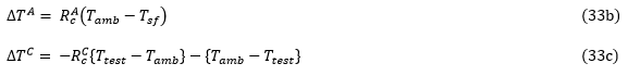
In Eq. 33b, { } are Macaulay brackets where {x}=0 for x<0, and {x}=x for x ≥ 0. Tamb is the ambient temperature specified in the *CURE STRESS keyword in the HIN file. If the temperature is not specified, Tamb is understood to be 72.5 °F, 22.5 °C or 295.65 °K depending upon the system of units used in the model. T is the temperature at which the test is performed (current temperature).
The right-hand side of Eq. 33b ensures that thermal residual stresses are correctly predicted at the end of the post-cure cool down to ambient temperature (i.e., when T=Tamb). The quantity RcA denotes the cure ratio for this step. By default, RcA is set to a value of 0.5. This default value is based on the work of Kenik [13]. Kenik showed that a simple linear elastic analysis using room-temperature composite material properties with an imposed temperature reduction of one-half the actual post-cure cool down, produces constituent thermal residual stresses approximately equal to those predicted by a more rigorous micromechanical simulation of the post-cure cool down using temperature dependent matrix properties. To adjust the value of RcA, refer to the Thermal Residual Stresses topic in the Ansys User's Guide.
The right-hand side of Eq. 33c ensures that any additional temperature reduction imposed after the post-cure cool down will produce the correct thermal stresses. Note that the use of the Macaulay brackets { } ensures the first term on the right-hand side of Eq. 33c contributes to ΔT only if the current temperature T is above the ambient temperature Tamb. The quantity RcC denotes the cure ratio for this step. By default, RcC is set to a value of 0.5. To adjust the value of RcC, refer to the Thermal Residual Stresses topic in the Ansys User's Guide. If the current temperature T is below the ambient temperature Tamb, no cure ratio is applied.
The total temperature change ΔT = ΔTA + ΔTC.
MCT Composite Material Characterization
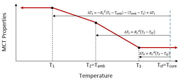
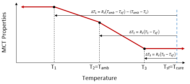
Eqs. 32 and 33 are also used during the MCT material characterization process for composite materials characterized at multiple temperatures. The image below illustrates a typical case where a temperature-dependent composite material has been characterized at three distinct temperatures T1, T2, and T3, where T1< Tamb, T2=Tamb and Tamb< T3< Tcure. It also shows the temperature change ΔT (computed via Eqs. 33a-c) that is included in the micromechanical analysis of the composite material at each of the three temperatures during the MCT characterization process. During the characterization process, these imposed temperature changes influence the determination of the constituent failure coefficients. For example, when the micromechanical model is mechanically loaded to a measured failure load level, the failure stress state in the constituent materials have contributions from both the mechanical loading and the imposed temperature change.
Current Environment:
Specify Environment: